
Introduction
In the middle of the summer we found an EV3 robot arm, so we thought to start developing some model based safety critical control program for it.

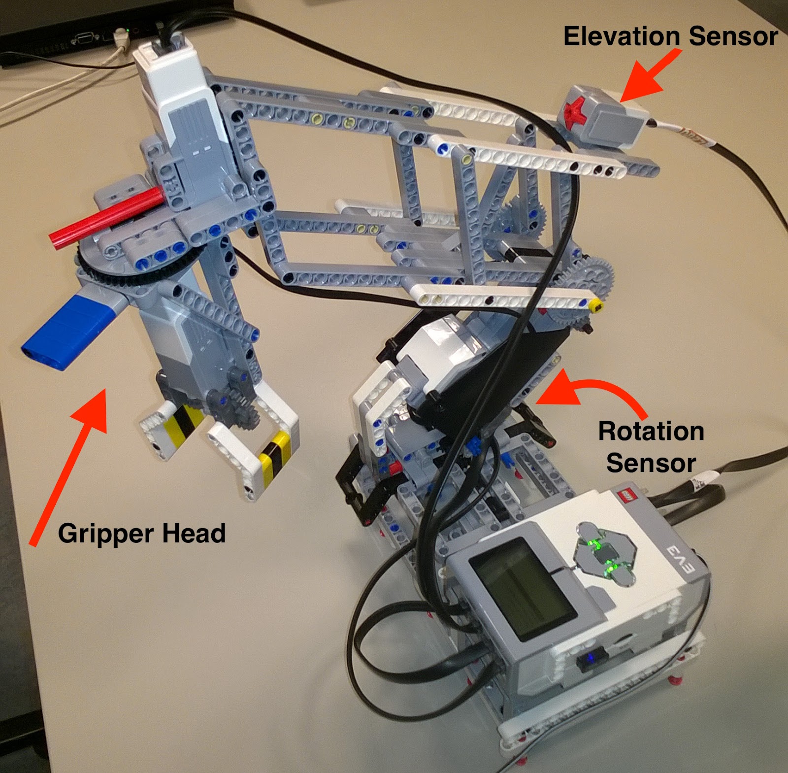
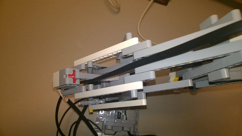
This robot had three motors and two sensors: one touch and one color sensor. It was built according to the step-by-step guide which you can find on this website. Later we have enhanced it by adding a new motor. With this new structure, as you can see in the picture below, we are able to rotate the gripper head.
We have implemented the control for the LEGO crane (robot arm) on top of multiple communicating components. The basic architecture is depicted below:
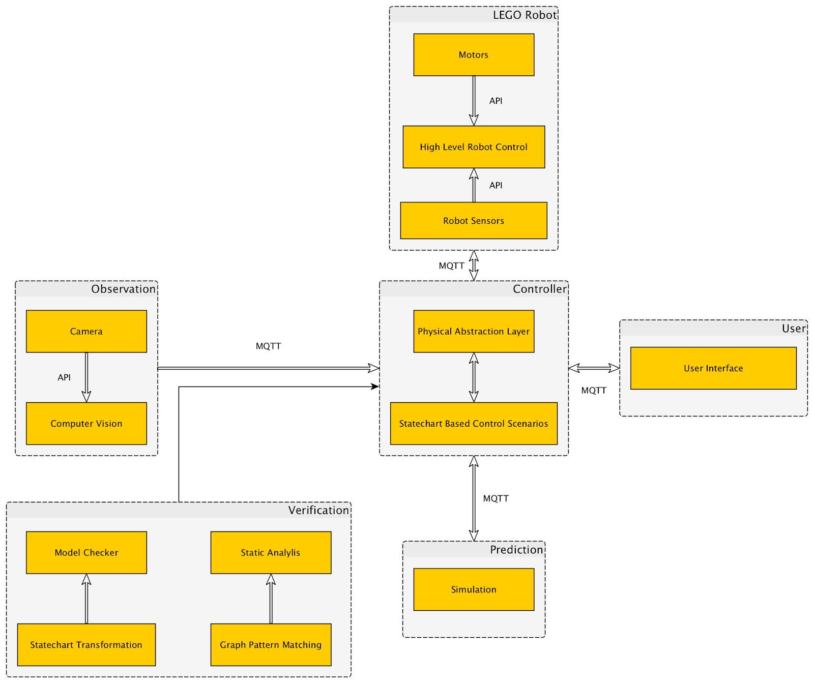
As it can be seen there are multiple functions in the system: Yakindu is used to develop the control with the help of statecharts, communication uses MQTT, the slave runs on the robot on an embedded processor. Simulation is used to predict movements, OpenModelica is used for these purposes. Computer vision and OpenCV gathers the information from the environment and sends alerts to the controller. In addition, it provides information from the object to be moved.
LEGO Robot architecture
In the first component you can see the EV3 itself. We have implemented a python script which directly controls the robot motors and is able to access sensor information or detect if the motor is overdriven. Generally, the python script receives commands from the controller component and executes them, although in order to prevent motor overdriving it also have some local reflexes. For example if any of the touch sensors is pushed, it stops all the movements automatically. As you can see in the pictures below, there are two touch sensors, one indicates if the robot arm moves too high, and the other if it wants to turn right too much. Some more details are provided in this blog post.

Communication
As I have mentioned, the controller component sends the control commands. But how does it do it? Almost all of these units communicate through MQTT. This protocol provides high maintainability and reconfigurability, so it made relatively easy to add new features. Every unit has its own topic where they publish and they subscribe to the other’s topics. We’ve developed hierarchical topics to organize the messages. This robot component only communicates with the controller component, which has other connections to the ‘user’, ‘observation’ and ‘prediction’ units.
User Interface
So let’s talk about the other units! It is obvious that we wanted to have control over this little robot, so we developed a graphic user interface in order to control its movements.

As you can see there’s no button for moving the arm vertically or horizontally, these functions are controlled with the arrow keys. This ‘user unit’ sends the commands to the ‘controller unit’ which processes them, afterwards sends a message to the robot. The GUI also shows the messages we’ve sent, and which we’ve received.
It is also possible to switch automatic operation. Here comes the logic question: what can this robot operate automatically? To be honest we have also found some model railway next to this robot that summer. So we thought the EV3 could move the cargos of the trains automatically. Obviously more help is needed for it, more information about the environment. That is why you can also see a monitoring component in the architectural view.
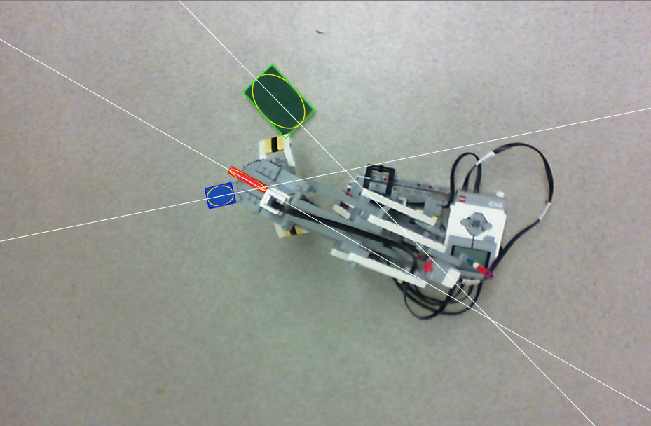
We observe the robot and its environment with a camera so we can analyse the situation in real-time using OpenCV3. This computer vision application sends messages to the controller. It warns the robot if an obstacle comes to the way. It notifies the controller if a train arrived to the desired place, this message also contains information about the orientation of the cargo. We can also ask for other information from it, for example the orientation of the gripper head, we use this function in the initialization of the robot’s motors.
For more details there is a more detailed blog post.
Controller
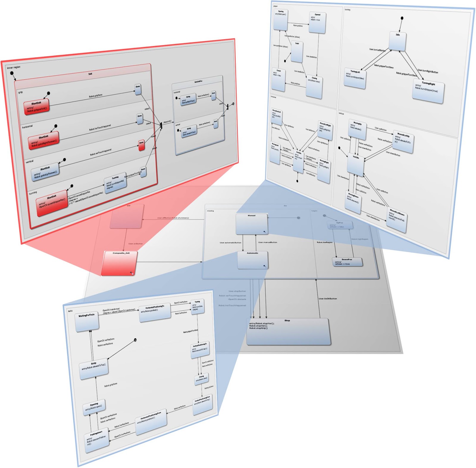
It’s time to see what the controller component does. This unit is responsible for the logic of the operation. We used the open source Yakindu Statechart Tools toolkit to model the control scenarios. The safety critical parts are implemented at first by state machines and then these design models are used for code generation: the produced source code can be deployed and integrated with MQTT to be able to communicate with the controlled objects. The controller also receives information from the computer vision parts and reacts to the events.
Yakindu statecharts has some useful features: the simulation of state machine models allows the dynamic semantics to be checked. Active states are directly highlighted in the statechart editor. In addition, Yakindu have many built in features for example validation rules which turned out to be very useful during the development. We also used the validation rules introduced in a former post to further increase the quality of the models, various analysis runs were conducted to check the design models!
Two kinds of composition rules were applied during the development of the control models. Yakindu tool provides built in hierarchy which we exploited in the design. We also decomposed the problem into two parts: one statechart provides the abstraction of the physical world and another statechart is responsible for the real control. This decomposition significantly increase the reusability of the control logic: for other robots with similar missions it would be enough to implement a new abstraction layer and the control logic could be reused!
Prediction
To compare the desired and the actual behavior of the motors we’ve used OpenModelica, an open-source simulation environment. The purpose of utilizing such a complex modelling tool was twofold: 1) design time analysis can help setting the parameters of the controllers. Estimations helped choosing the proper parameters for the controllers. 2) Runtime prediction can be built on top of the modelica models. Asking information about the limits of the robot in certain situations turned out to be helpful. Especially in those situations could we benefit from the simulation results, when the mission reaches the limit in a direction where no sensor information is available. In those cases simulation can predict the rotation value which is still safe for the system.
For more information read this post!
Validation & Verification
The controller of the robot arm was developed with the help of Yakindu statecharts. Validation rules provided by the tool and also by ourselves helped to find problems early in design. Verification was also done by transforming the design model into a formal representation and analysing simple reachability queries on it.
Summary
We have developed a the control of a Lego robot. Computer vision is used to observe the environment and provide autonomous behaviour of the robot. Simulation is used at design time to estimate the necessary parameters of the control and at runtime to check dangerous movements of the robot arm.

Various IoT and model based techniques were implemented in the project, the synergies of these technologies led to a complex IoT application!