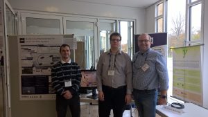
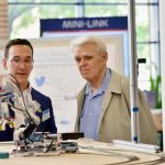
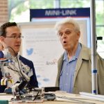
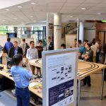
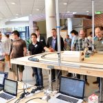
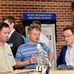
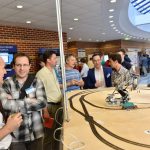
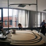
Our team presented a demo at the EclipseCon IoT playground.

Model-based Demonstrator for Smart and Safe Systems
Our team presented a demo at the EclipseCon IoT playground.


What Makes an Open IoT Developer Challenge Winner!
MoDeS3: Promotional video
As we mentioned in a former post, Bence, who is our colleague, has developed a model transformation plugin for YAKINDU as well. The plugin transforms a chosen SCT model into timed automata, and automatically generates CTL expressions for formal verification.
Let’s have a look at its theoretical background and a practical example.

The workflow of the transformation is depicted above. First, the YAKINDU Statecharts to UPPAAL Transformation Engine parses the Statechart design model (the SCT file), and looks for different mathces of structural graph patterns in it.
The patterns were composed in the Query Language of EMF-IncQuery. For composing these patterns the metamodel of the YAKINDU Statecharts were used, because the statcharts in the SCT model are the instances of that metamodel.
After that, the Transformation Engine transforms the given statecharts to timed automata acceptable by UPPAAL. In order to achieve it, we used the metamodel of UPPAAL. The metamodel is publicly available and was designed at the University of Padernborn. The transformation code was written in Xtend and it extensively uses the EMF Reflective API.
Finally, the Transformation Engine creates UPPAAL automata that adhere to the statecharts, and generates CTL expressions to make model checking automatic. You can find details on model checking in a former blogpost.
Now let us show you in an example what our YAKINDU Statecharts to UPPAAL Transformation Engine is capable of. First of all, we need a Yakindu model that we want to transform. We have made a simple timer statemachine just for this demonstration.

As you can see, the model consists of two states. In Idle state the system does not do anything. In Running state the system measures time. Also, there are two events that can be used for controlling the system. Finally, there is an integer variable that symbolizes elapsed time.
Let us transform this statemachine to UPPAAL. This is what we get:

Control template:

As you can see, the transformer creates two templates. The first one is the UPPAAL equivalent of the YAKINDU statechart. The second one is a control template that is used for firing events.
Let us see what transformation rules the transformer uses:
So what can we use this UPPAAL model for? First, you can run simulations on it. With the control template you can fire events, so transitions and actions can take place in the primary process. You can see the actual active locations of templates, you can follow changes in values of variables etc. Here is a picture of a simulation on the timer model:

Second, queries can be created for checking certain properties of our models. Let us say you want to know whether your statemachine is able to reach a certain state, or a value of a variable can be negative. You just have to create a query that describes the condition and the Verifier will tell you whether it is possible or not in your model. If it is possible, even a simulation trace is created that shows you the transitions taking your model into the certain state. Let us show you some queries:

The first query checks whether there can be a deadlock in the system. Fortunately, the model has been designed well, so deadlocks cannot take place.
The second and third queries check whether Running or Idle states can be reached. We create states because we want to reach them. If a state is unreachable, then something is wrong with the model.
The fourth query checks whether time can be measured for longer than 9 seconds. We created this model to measure time, and according to the Verifier we can do so for at least 10 seconds.
The fifth query checks whether the elapsed time can be a negative value. If it was possible, then something would be very wrong with the model. Fortunately, this is not the situation now.
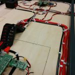
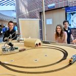
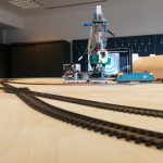
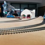
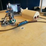
In the last couple of weeks we have finished the open IoT Challenge submissions. One showed a control system for a Lego robot arm which executes missions. The control logic was developed with model-based development tools, computer vision observes the environment, simulation is used at design and also runtime to analyse the behaviours. Various open-source technologies were used to ensure the interoperability of the system. The full summary is available: http://modes3.tumblr.com/post/140068568675/modes3-lego-robot-the-summary
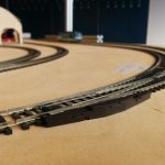
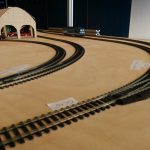
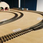
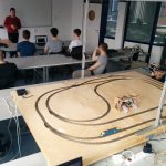
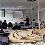
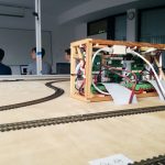
The second submission showed the development of a mixed-critical system, where various technologies were used to ensure the accident free behaviour of a distributed railway system. Beside the many open-source technologies we employed, also various verification techniques were used in the project, namely testing, runtime verification and model checking. For further details, please read our post: http://modes3.tumblr.com/post/140068608695/modes3-railway-system-summary-of-the-project
Note that in conclusion, the Lego robot arm is placed on the table of the railway system, so the whole system is built on top of two sub-systems executing different missions.
All the developments are detailed in our blog! For further questions, do not hesitate to contact us!
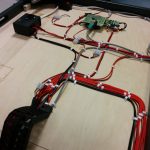
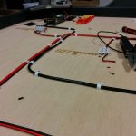
Now, that the Open IoT Challenge is over, we have some spare time, therefore I try to explain for you how the hardware works and how was made. It won’t be a very long post, you shouldn’t read long paragraphs about electrons or voltage, but I will insert a tons of pictures into it, I should insert a read more link here. But trust me: it is worth watching them!
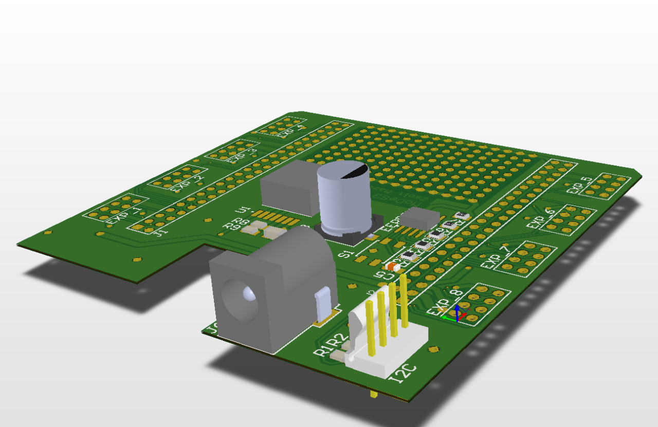
Previously one of my colleague, Bálint already wrote about why the Beaglebone Black board is so amazing, but in an other post I mentioned our little problem with the hardware – so I did managed to make a Cap for the beagle to make it Superman Superbeagle.
The design:
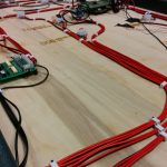
And the reality:
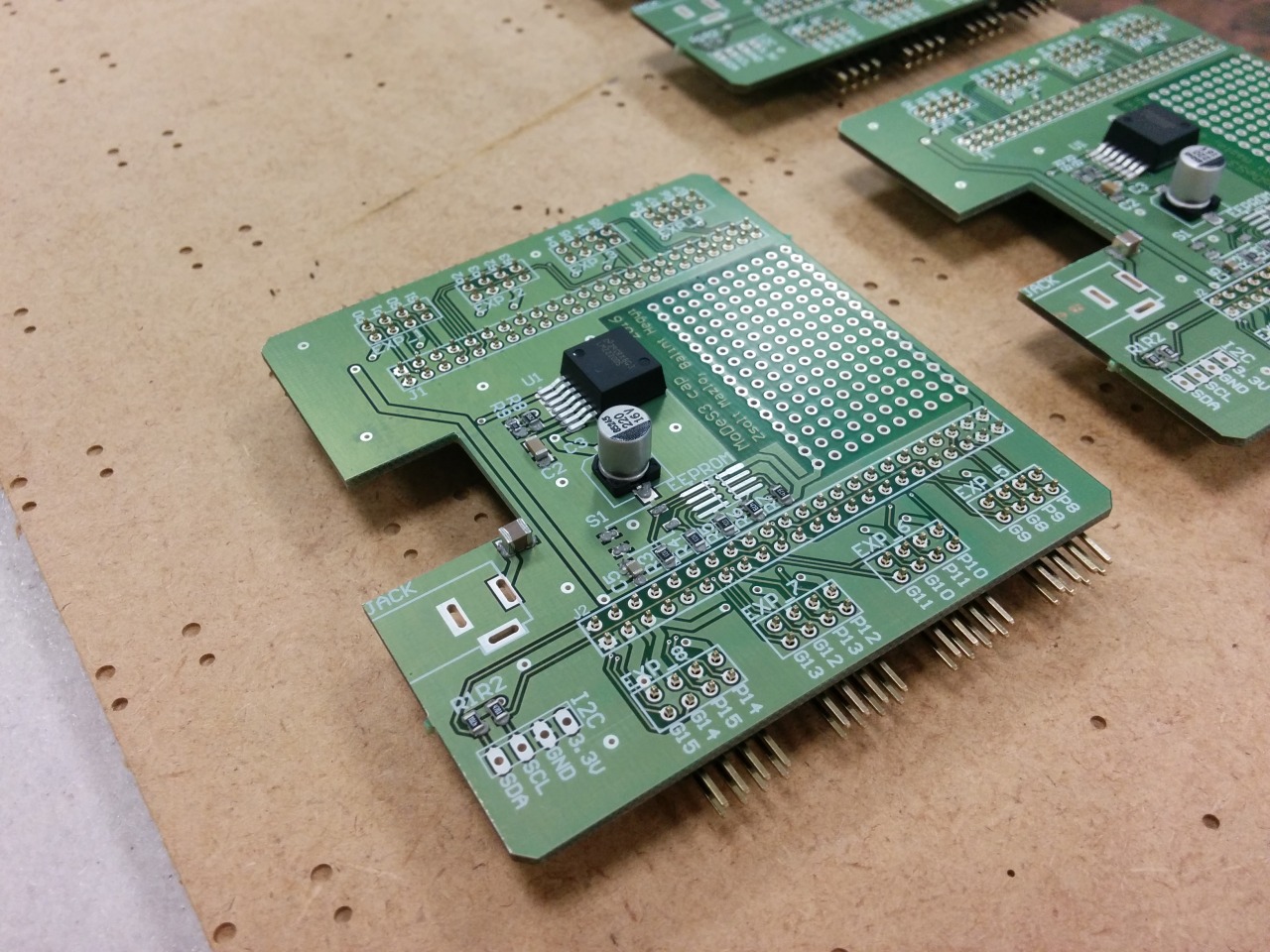
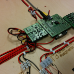
With this Cap, the Beaglebones could accept any power source between 7V and 20V, we have 8 pin headers to attach expander panels… oh wait, did I mentioned that we designed expanders also? No? My bad.
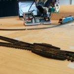
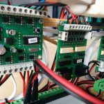
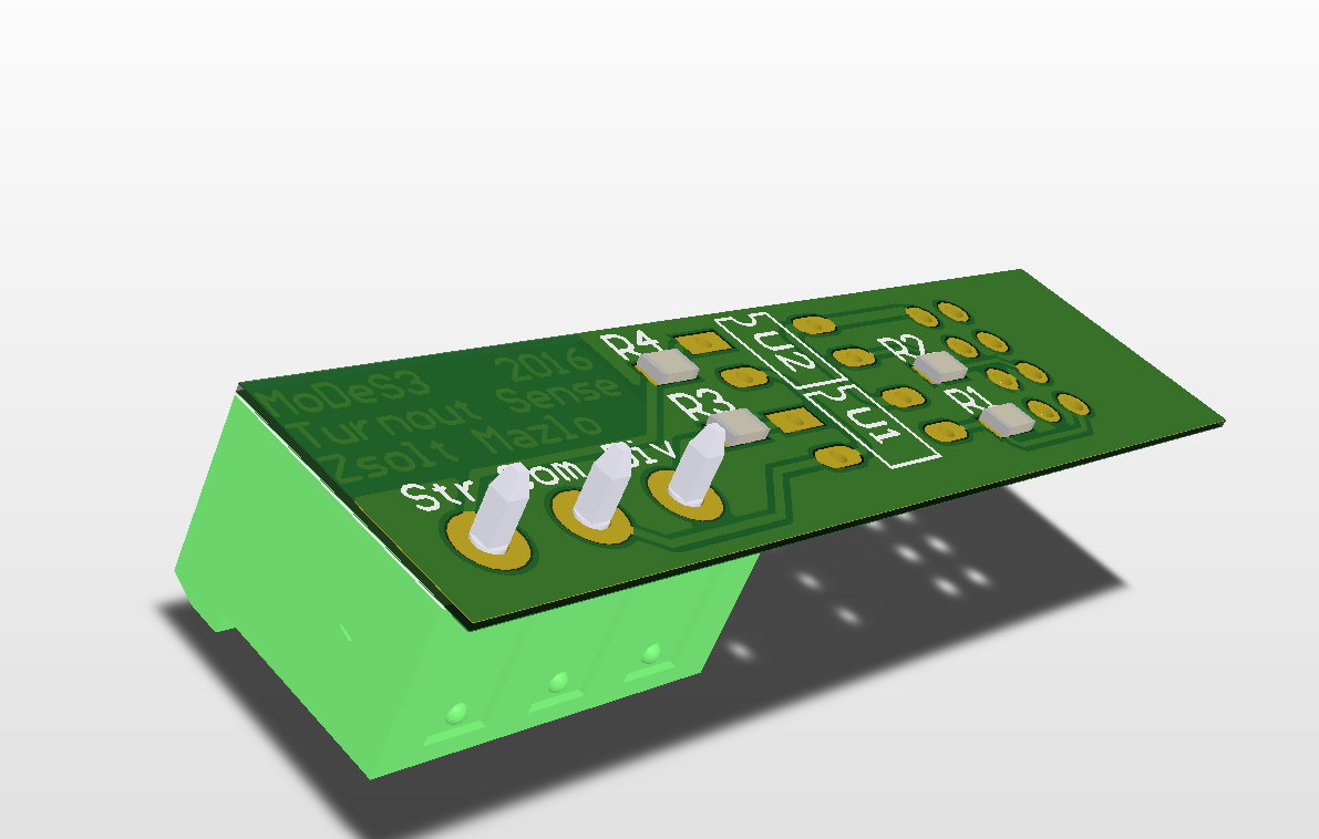
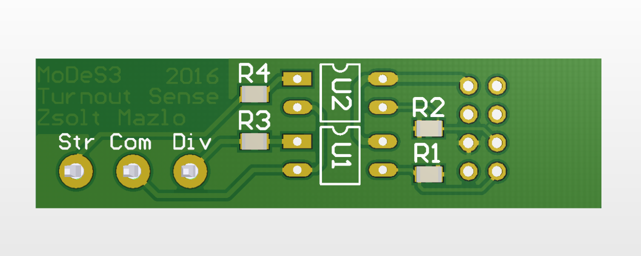
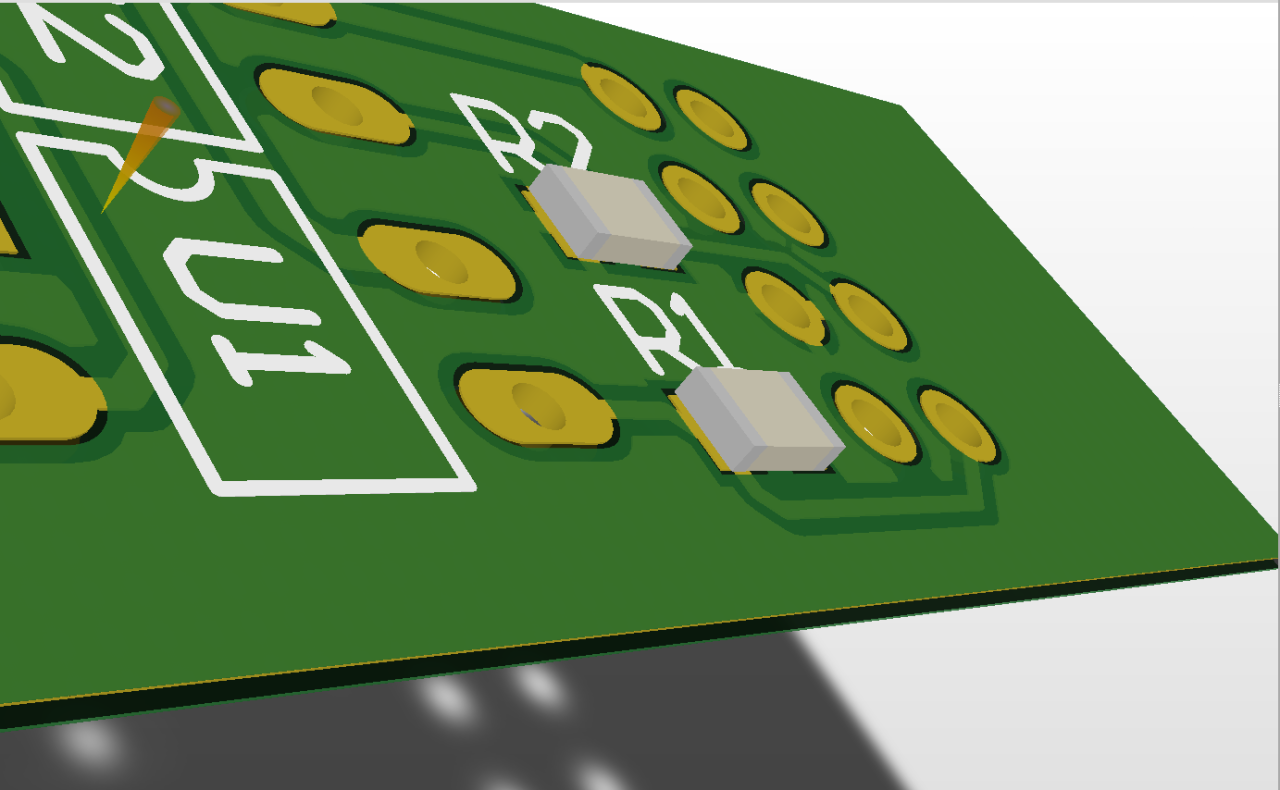
One of the many responsibility of the hardware is that it need to sense somehow the status of the turnouts. These informations are highly important: some cases, in which trains are moving towards each other, they could collide, so we should stop them; but if the turnout is in the right position, then we could pass one of them through the turnout and even avoid the collision. With this knowledge, we could make the movement of the trains continuously beside the safe operation.
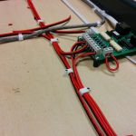
Therefore we made some measurements about how the turnout actuators are work and after that we created a PCB to handle this.
Here is the design:
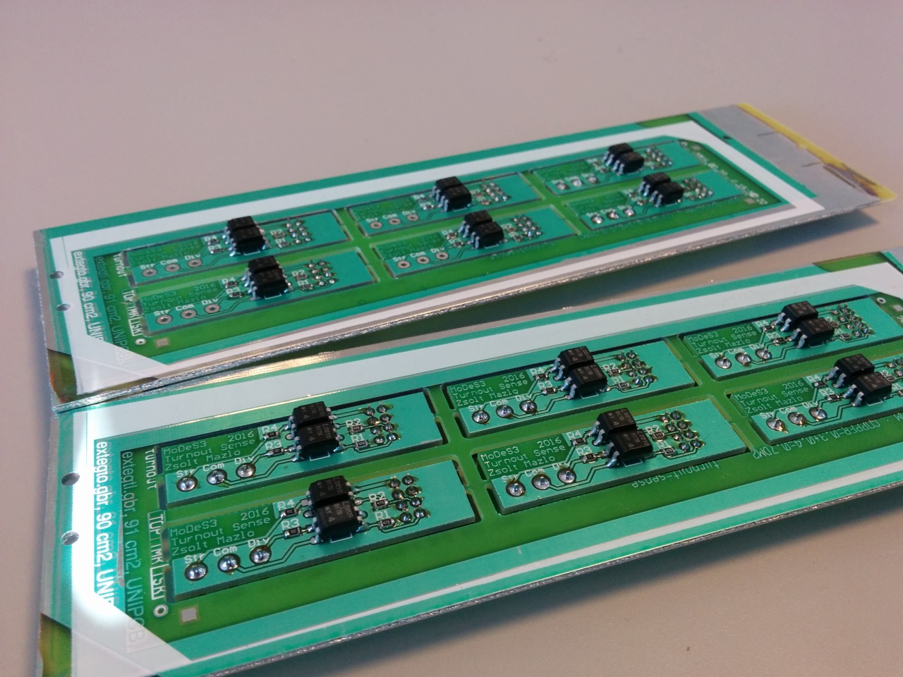
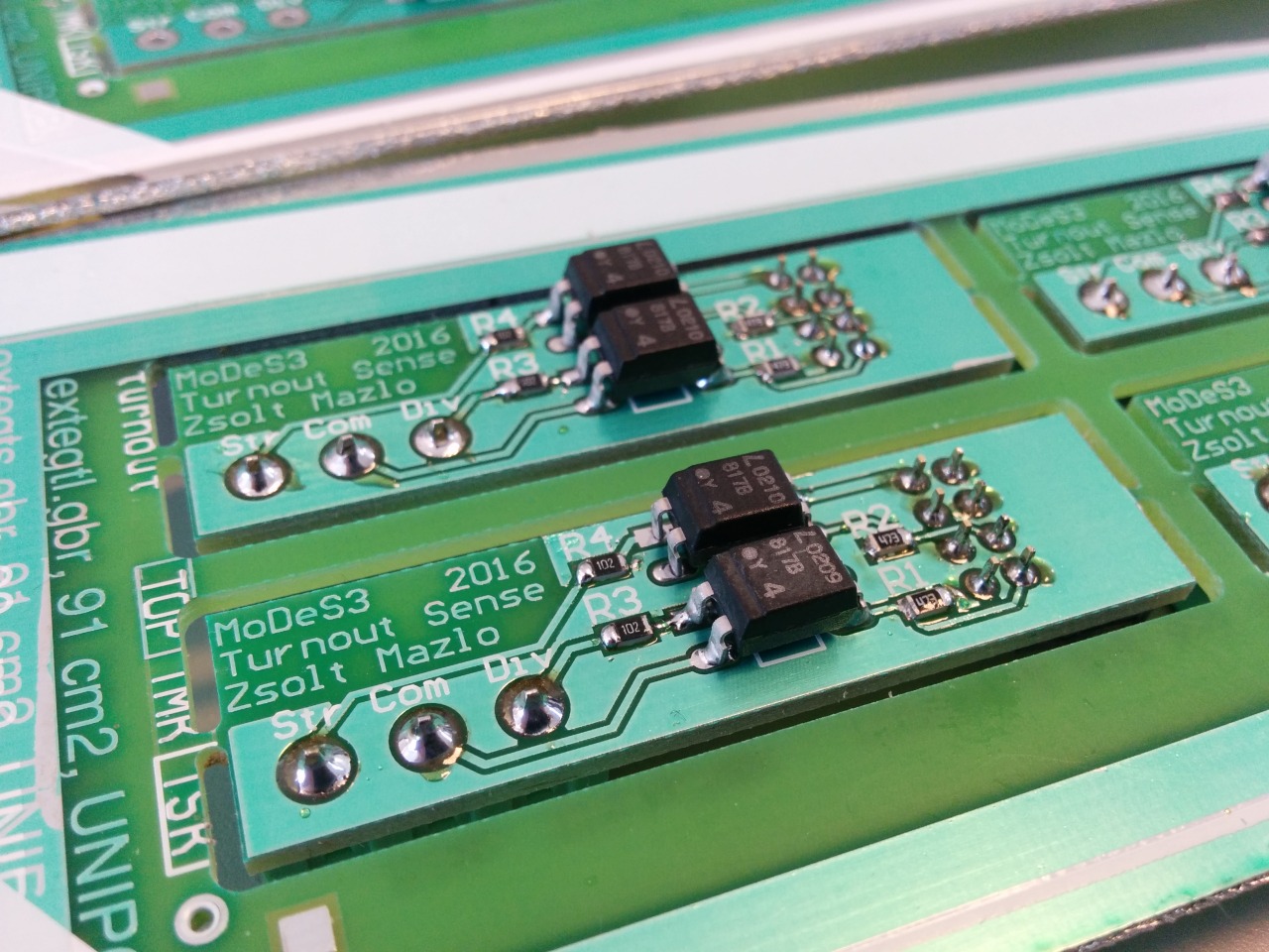
And the reality:
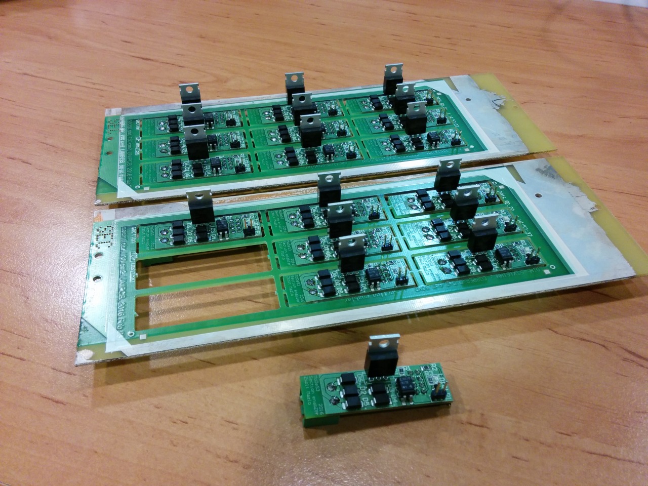
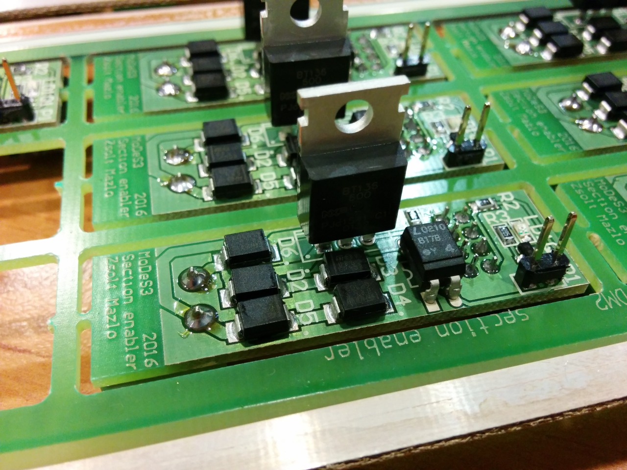
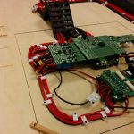
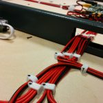
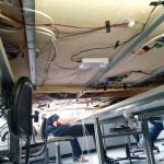
Okay, let assume that we are getting every information about the track that we need: the location of the trains, the turnouts’ status, and so on, and one time, we need to stop one train: but how, you may ask. That’s the reason why we designed and assembled the section enabler or disabler PCBs: in the near past I wrote about the mechanism.
Design:
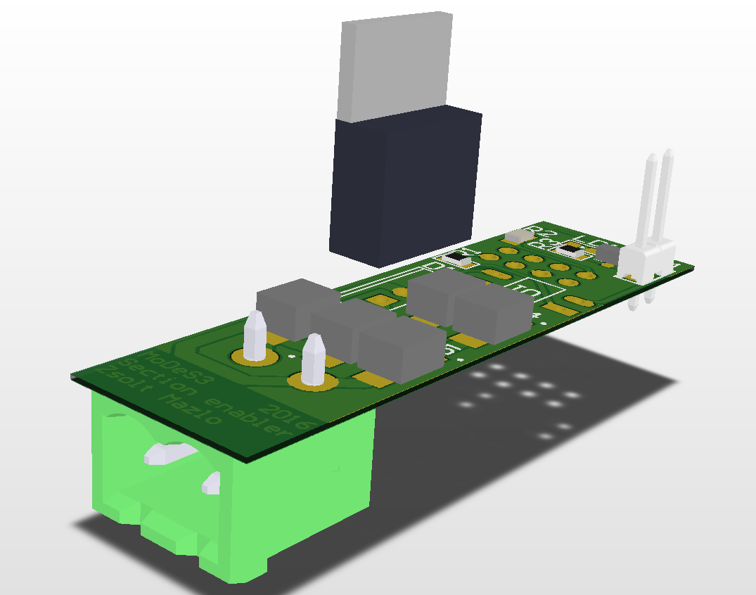
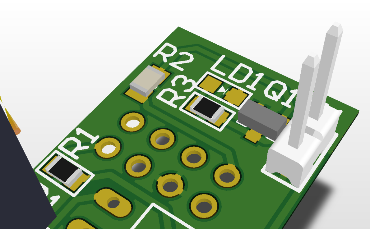
Reality: