
Model-based Demonstrator for Smart and Safe Systems

Before we start to post videos, photos and other stuff about this project, I may say something about this project’s history.
It started back in 2014, when we jumped into a project to desing embedded systems and a model railway demonstrator. So with one of our member, Benedek, we started to build something. We literally had no experience with embedded systems neither with model railways, so the first attempt to create this system – let’s be honest – failed. We wanted to use model based techniques for the development, but we were not able to upload any complex, generated code to the system, which was based on Arduino Ethernet boards. We could only use hand-written code with small complexity.
Intermezzo: why we choose Arduino for the first place? Because I was the one who had some experience with embedded systems, and I only knew Arduino, and needles to say, I was convinced that it would do the work.
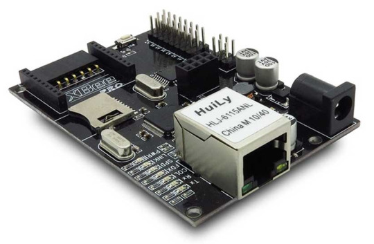
Furthermore, these units (like one on the picture) were so customized ones that even uploading code was a disaster – I don’t know what we did wrong, but our serial-converters which needed to upload the code were starting to die after a short time of usage.
But, either way we managed to implement an interface for the layout to be able to stop trains. We could read from the layout where the trains were, but nothing more. So our safety logic was a bit harsh with the trains – they had to be stopped a lot. This was the time when we realized that we need the proper hardware for this project. And then we could speak about any further developments.
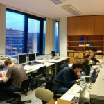
But, we worked a lot, we had some results in the field, so we went to the Researchers’ Night to present the system. There we showed this small and stupid system to people, we talked about it, showed it to kids and adults and tried to brought them closer to IT. And grab their attention.
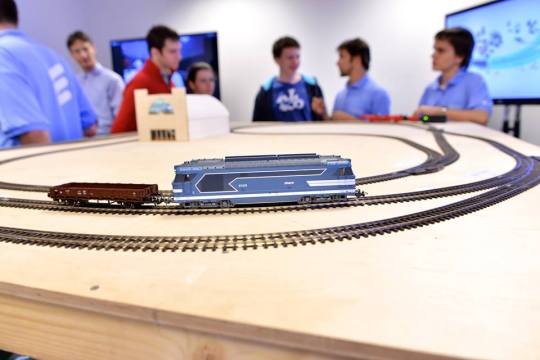
It was a huge success, I think I could say that they loved it (especially the kids). We were really happy with the feedbacks, so we decided to enhance our system, change the components and the software and to build a completely new sytem on top of the former experiences.
And that’s where the IoT Challenge came across.
Because when we heard about this challenge we decided – we are getting back to square one, start to redesign everything (beside the track), start to make better plans, make more research about embedded systems, modern techniques and make a project which could be really used to demonstrate the model based development of complex systems.
zsoltmazlo
In the following, I will overview the past and the future of the hardware we use in the project!
At the post “What this project was all about”, zsoltmazlo described the application of Arduino boards. The choice was based on the experience of easy usage of the libraries, but later during the development of the models it turned out that they hit their limitations.
As you may know, the Arduinos are basically microcontrollers. They are really an all in one package. But with microcontrollers, the programmer is facing very serious limitations. The Atmel ATmega328P has 32 Kbytes of program memory, and 2 Kbytes of data memory, with a 20 MHz operating frequency. This is the processor on the well famous Arduino Uno, and we also had Ethernet capable board. But the memory limitations are serious.
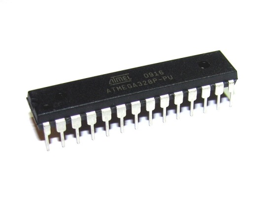
Comparing this with even your smartphone: just lack of performance. However, we have to mention, that although they look quite weak, they are very usable. 98 percent of the computers are used in embedded systems, and most of them utilizes microcontrollers like the one I mentioned.
Well, than what was the problem? We develop in a model-based fashion. With a safety critical system, you can’t just write code, and hope it just works, or test it to a level where the developer thinks it’s safe enough. You need mathematical proofs of the correctness of your solution, and you can do it with model based developement. You create some abstract representation of your application with statecharts, flow diagrams, or other abstract representations (read the post “Statecharts are everywhere!” if you are interested). These are mathematically more representable objects, therefore we can analyze this.
So what is the bottom line? When you are ready with analyzing the correctness of your model, you somehow need to make this model runnable. From a model, you can generate code (e.g C, C++, Java, etc.), so you can compile and run it. The problem with these code generators is that they are not prepared for the limitations of an embedded system: generated code is used to use dynamic memory handling, and trash a little. So little, you wouldn’t notice this in a PC, but with 2K RAM, you will, and the application will crash because it can’t allocate more memory for itself.
It turned out that to overcome these difficulties might be much harder than upgrading our hardware to the next level, so we chose the latter, and started developing the new hardware to suit our needs. Sure, we could work out how we could generate code to fit inside, but the MoDeS3 project isn’t about just us. It’s a tool to develop safe and smart applications, and the hardware needs may be varying between projects, so it is just better to fit the future needs.
Coming up: the new hardware and the horizon is opened for us!
Bálint
Even it’s holiday, what’s more it’s sunday, we can’t stop working on our project, because we are so excited!
I’m Benedek, the ‘state machine expert’ of the team. I’m responsible for the so-called ‘safety logic’. That is a statechart based control, which supervises the trains and intervenes to prevent collision.
The safety logic was designed in xtUML BridgePoint Editor. It offers a model-driven design environment for developing embedded software. It is based on the xtUML methodology, which means that the created UML models are executable and translatable. This way direct translation from UML to a target language and platform, for example C, C++, Java can be easily achieved. The best comes yet: it’s free and open source! Check it out at xtuml.org!
The class diagram is depicted here:

It is quite complicated, so I describe it in short. Section and Turnout (or switch in better terminology) were differentiated.
Section can be FreeSection if no train is on it, otherwise it’s OccupiedSection.

The behaviour of the FreeSection is quite simple, it simply allows any train to come to the section. Because its so simple, it is not depicted now. 🙂
But, the OccupiedSection is more interesting, because it contains a more complex logic in itself:

As you may see, there is some text in the squares, that are called states. The edges connecting the states are called transitions, which have events or triggers written on them. If an event is occured in a state, then the respective transition is fired, which means the state machine moves from one state to another.
As an illustration: in BridgePoint one can write platform independent actions, in the BridgePoint’s own language, called OAL (Object Action Language). With the help of actions, we can create and fire events, instantiate new state machines, create references between objects, and so on. Actions can be written within edges and states as well.
E.g. in the BecomesLocked state the next OAL code is written:
select one section related by self->Section[R1];
send Port1::setSection(sectionId: section.id, isEnabled: false);
It gathers a reference for a section, and sends a setSection event with several parameters through Port1.
A Turnout can either be Straight, or Divergent. It is illustrated on the following picture (the recent direction is marked with black):

The logic for the Turnout was designed in a three-level hiearchy (see the high-level class diagram on the top of this post!). Only one column of the hierarchy exists at a time, depending on the recent direction of the turnout (or switch).
The first level is responsible for rejecting new events that are received while a former event is being handled by the hierarchy.
The second level is responsible for handling events which are received from perpendicular direction than the turnout’s recent one.
The third level is actually responsible for what we call safety logic itself.

It is quite complex, but on high-level it can be described easily; we have to stop trains if they are close to each other. On this level we are prepared for the worst-case scenario, which means the trains are approaching to each other!
Trains are either in the territory of the local turnout, or a remote one. Thus turnouts have to communicate with each other, whcih adds an extra complexity to the system.
Ugh, it was quite a long post, but we hope you liked it, and found the state machines fascinating.
New posts are coming soon about the hardware architecture and the safety logic, which are being developed at the moment! 🙂
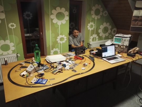
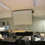
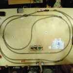
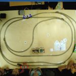
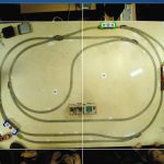
We happily announce our first evidence of working!
One of our
teammate, Bálint went home yesterday (he lives 2 hours away from the capital city) and brought the necessary components of the railway with him to
work out the basic electronics – we need to stop the trains somehow!
Of
course his younger brother is also affected with IT and electronics, so
Bálint has a “crew” to work with – even if he does not want a crew. So they are working on a circuit that could stop trains with a signal provided by an embedded system.
zsoltmazlo
First of all, thank you for visiting this site – I’m sure you are familiar with one team-mate and you came here because he is advertising this site, but hey, you are here! So you may be interested in our project, and that’s fascinating, wo-ho!
So basically this project is motivated by our participation in IoT Challenge 2016 and we are making a blog about it. Doing a blog was our plan anyway, so it’s not a big burden for us. We are building a safety-critical system for a model railway, where mixed criticality components work together. But for further details you should follow this blog. We hope you will enjoy it!
Cheers,
MoDeS3 team