What Makes an Open IoT Developer Challenge Winner!
(Source: https://www.youtube.com/)

Model-based Demonstrator for Smart and Safe Systems
What Makes an Open IoT Developer Challenge Winner!
MoDeS3: Promotional video
In the last couple of weeks we have finished the open IoT Challenge submissions. One showed a control system for a Lego robot arm which executes missions. The control logic was developed with model-based development tools, computer vision observes the environment, simulation is used at design and also runtime to analyse the behaviours. Various open-source technologies were used to ensure the interoperability of the system. The full summary is available: http://modes3.tumblr.com/post/140068568675/modes3-lego-robot-the-summary
The second submission showed the development of a mixed-critical system, where various technologies were used to ensure the accident free behaviour of a distributed railway system. Beside the many open-source technologies we employed, also various verification techniques were used in the project, namely testing, runtime verification and model checking. For further details, please read our post: http://modes3.tumblr.com/post/140068608695/modes3-railway-system-summary-of-the-project
Note that in conclusion, the Lego robot arm is placed on the table of the railway system, so the whole system is built on top of two sub-systems executing different missions.
All the developments are detailed in our blog! For further questions, do not hesitate to contact us!
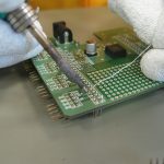
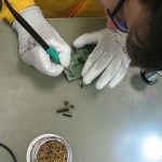
Now, that the Open IoT Challenge is over, we have some spare time, therefore I try to explain for you how the hardware works and how was made. It won’t be a very long post, you shouldn’t read long paragraphs about electrons or voltage, but I will insert a tons of pictures into it, I should insert a read more link here. But trust me: it is worth watching them!
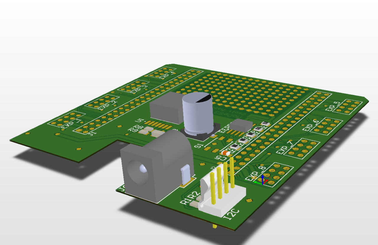
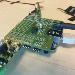
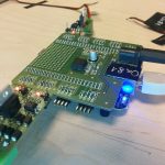
Previously one of my colleague, Bálint already wrote about why the Beaglebone Black board is so amazing, but in an other post I mentioned our little problem with the hardware – so I did managed to make a Cap for the beagle to make it Superman Superbeagle.
The design:
And the reality:
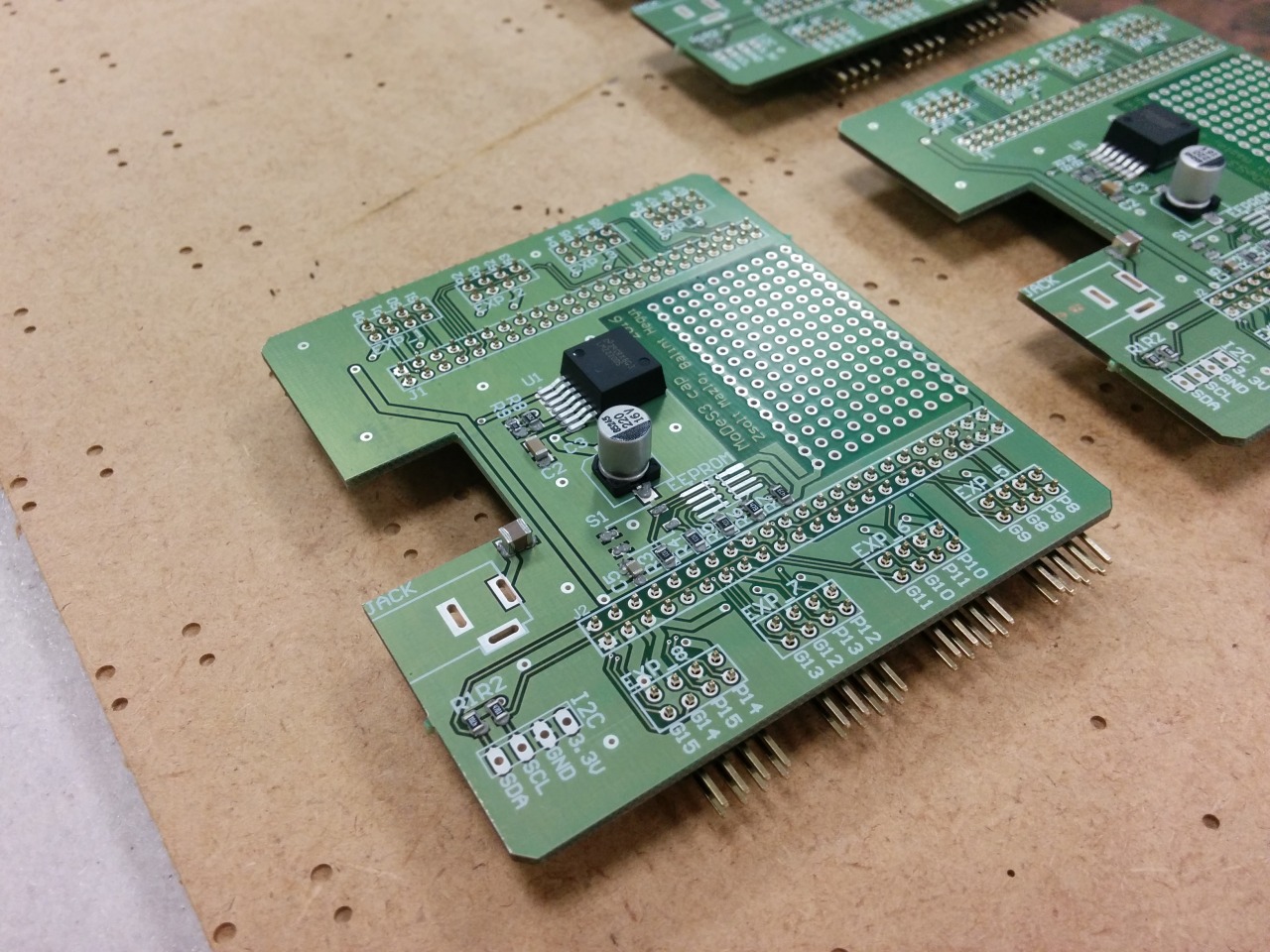
With this Cap, the Beaglebones could accept any power source between 7V and 20V, we have 8 pin headers to attach expander panels… oh wait, did I mentioned that we designed expanders also? No? My bad.
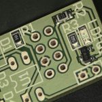
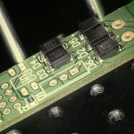
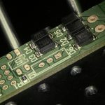
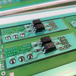
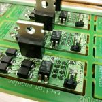
One of the many responsibility of the hardware is that it need to sense somehow the status of the turnouts. These informations are highly important: some cases, in which trains are moving towards each other, they could collide, so we should stop them; but if the turnout is in the right position, then we could pass one of them through the turnout and even avoid the collision. With this knowledge, we could make the movement of the trains continuously beside the safe operation.
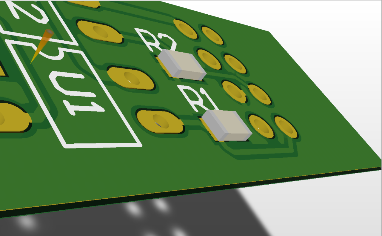
Therefore we made some measurements about how the turnout actuators are work and after that we created a PCB to handle this.
Here is the design:
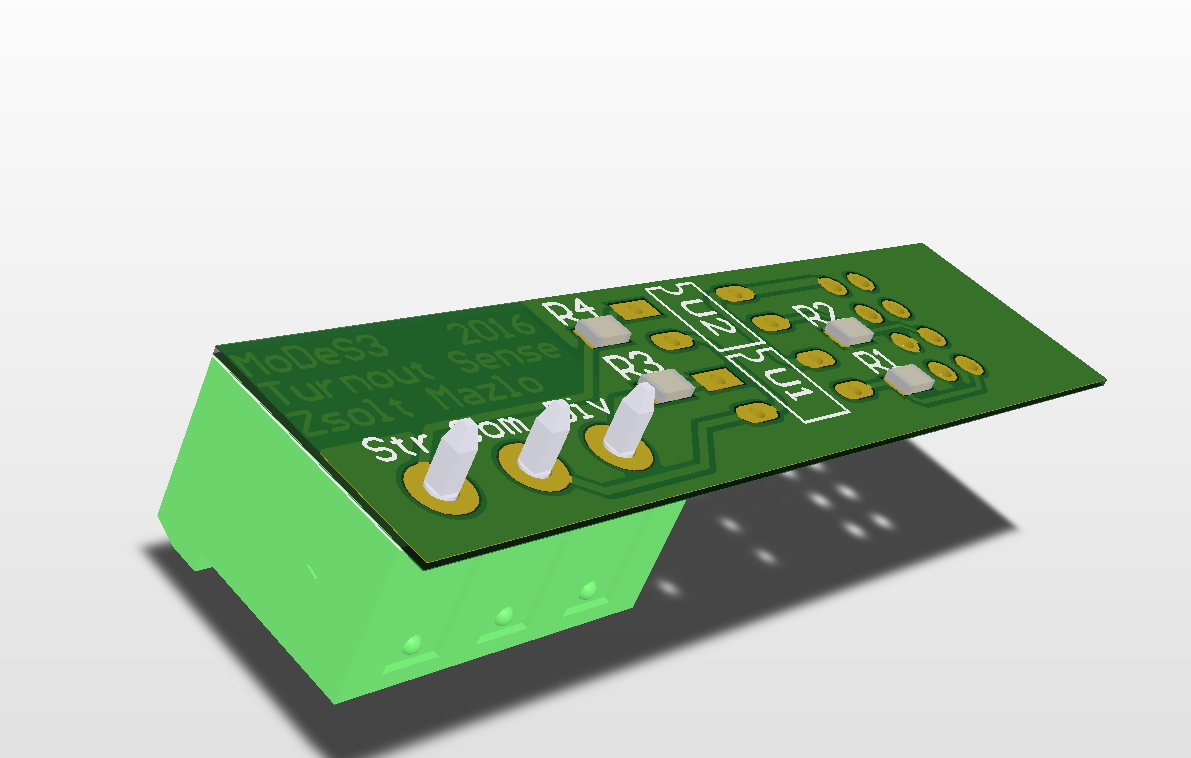
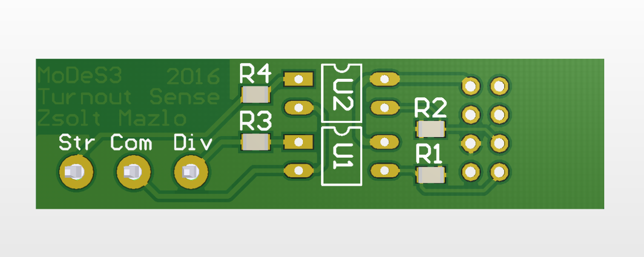
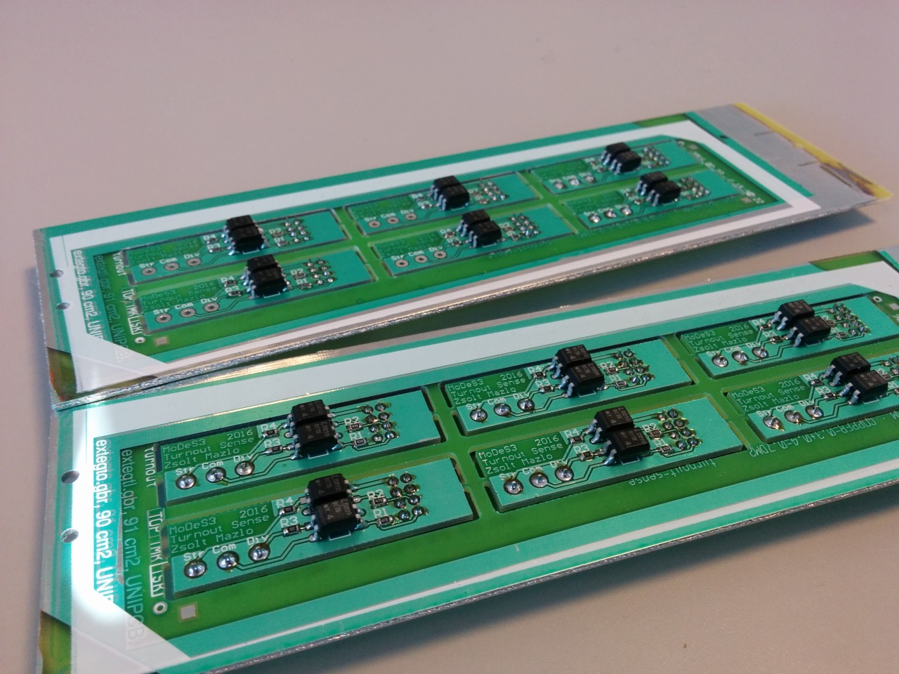
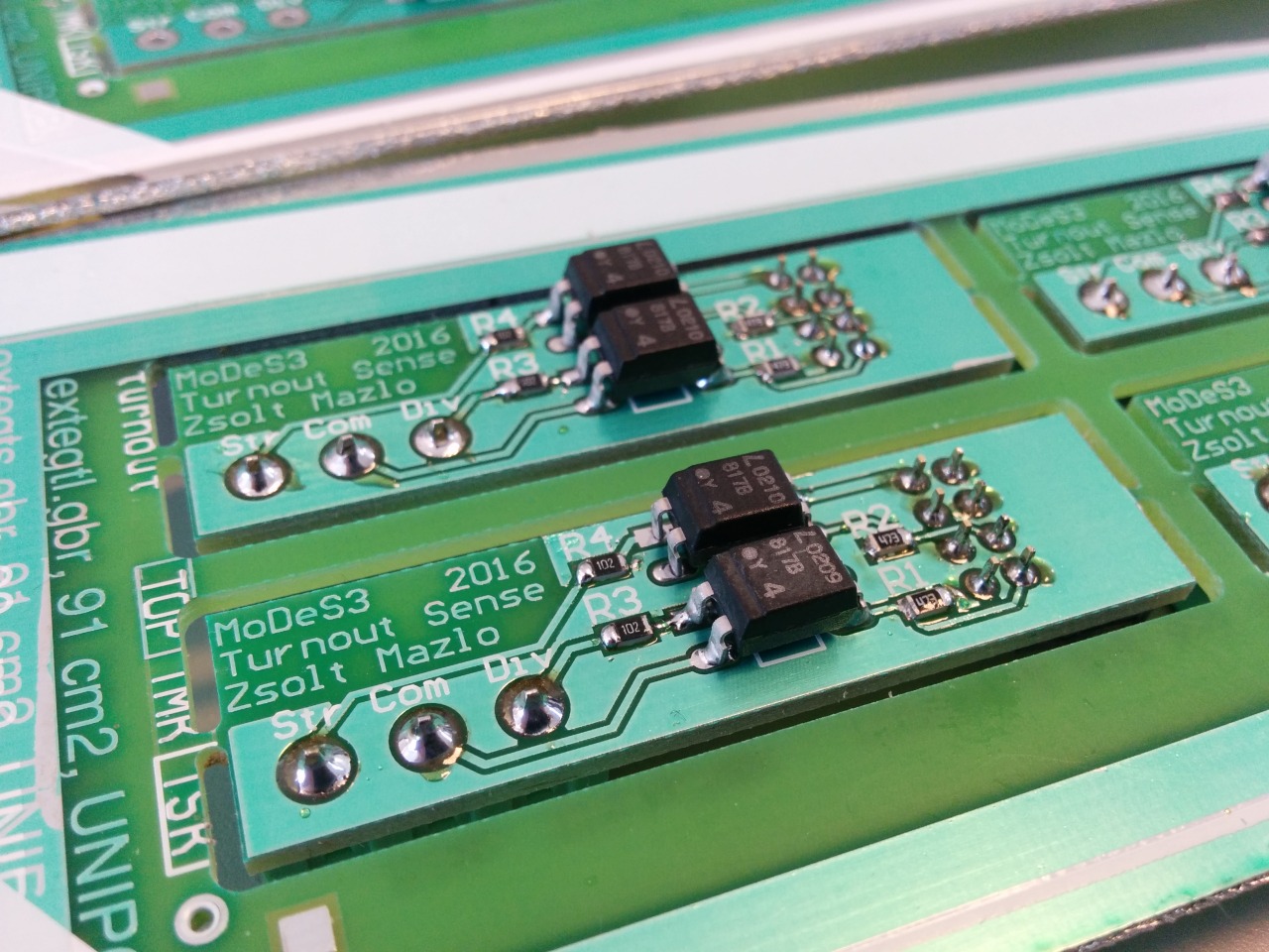
And the reality:
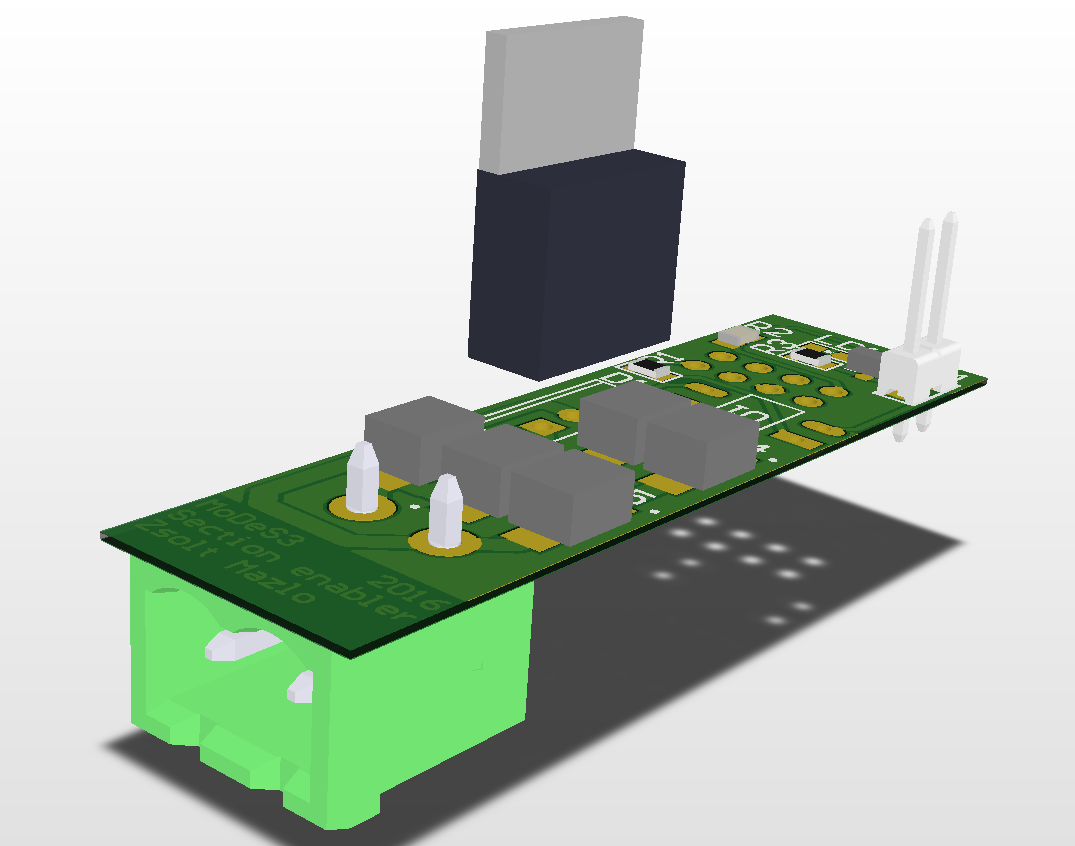
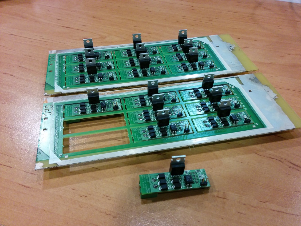
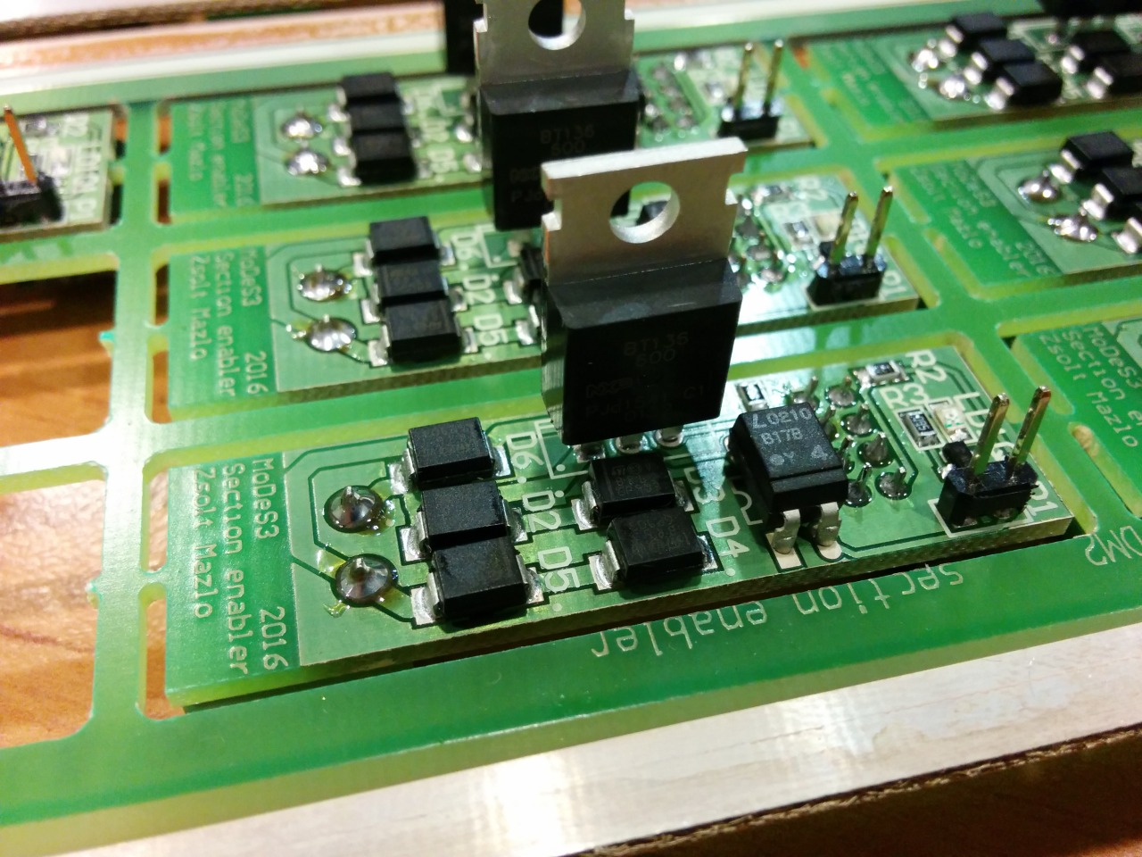
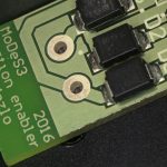
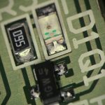
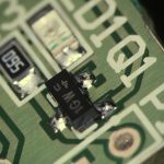
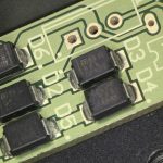
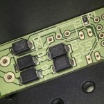
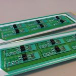
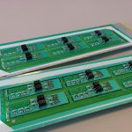
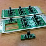
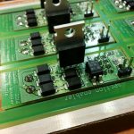
Okay, let assume that we are getting every information about the track that we need: the location of the trains, the turnouts’ status, and so on, and one time, we need to stop one train: but how, you may ask. That’s the reason why we designed and assembled the section enabler or disabler PCBs: in the near past I wrote about the mechanism.
Design:
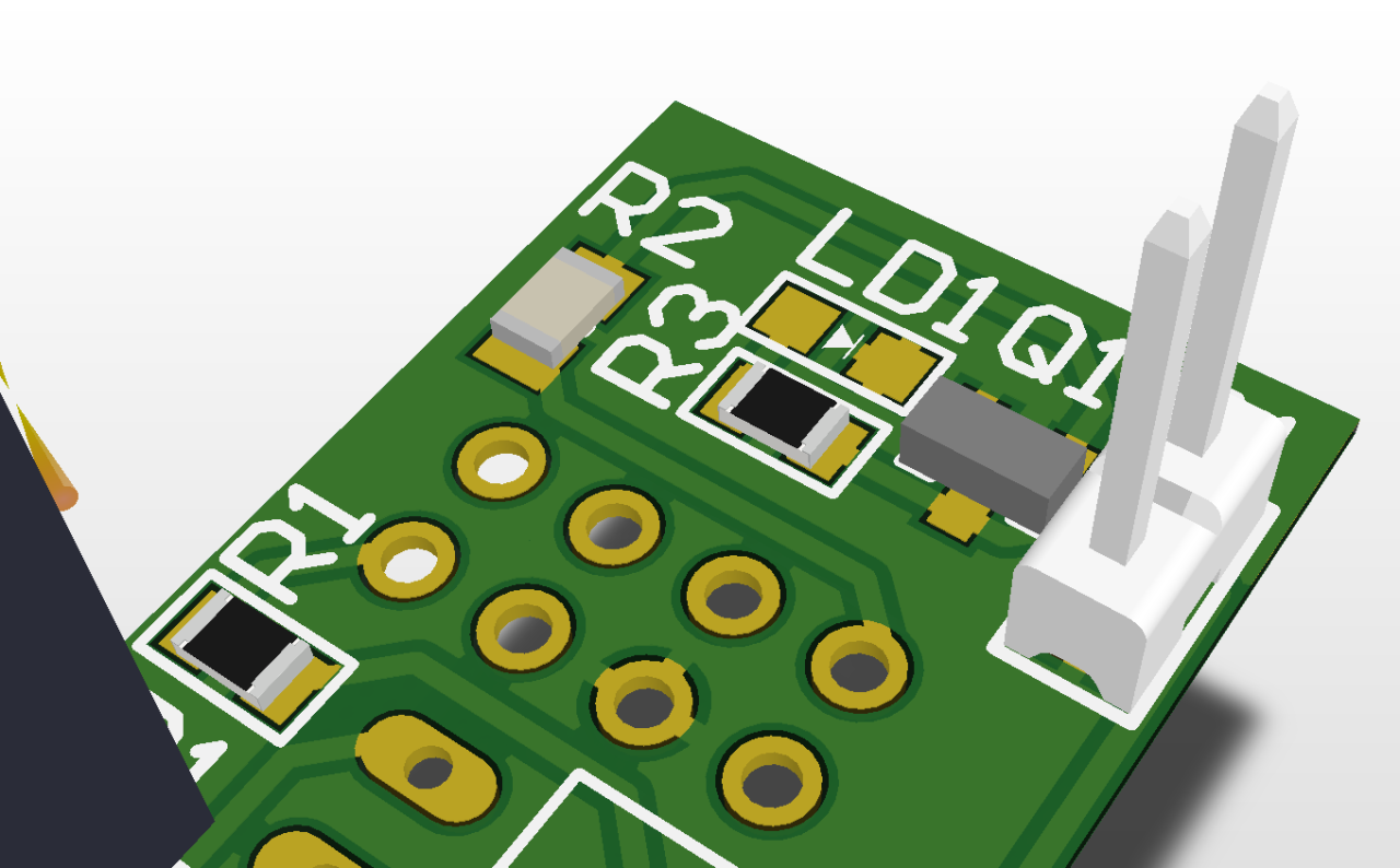
Reality:
MoDeS3: Lego robot video
Finally the trains were stopped!
In the last two months we have invested much time to demonstrate model-based development with the help of a mixed-critical model railway system. We wanted to show the newest techniques that can be used to develop highly reliable safety critical systems.
We started from an old hardware architecture, but for this project we have completely redesigned the hardware architecture to meet the new requirements of the envisioned system – we wanted to demonstrate various development, verification, and validation techniques, integrate them, and use a real-time open-source operating system on the controllers. After the architectural plans were made, we’ve decided to use BeagleBone Blacks that’ll run a special Debian based Linux (with a real-time kernel developed by Texas Instruments).
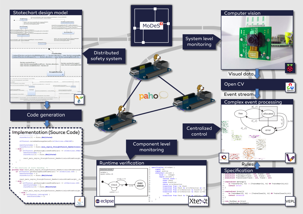
The development of safety critical systems starts by clarifying the requirements – in this case our goal is avoiding crashes and accidents. Then comes the more difficult part: model-based development of the distributed logic. This allows verification and code generation based on the model, resulting in a more reliable system. This was conducted in the open-source Yakindu Statecharts Tool. Validation and verification rules were utilized to find design problems at the early stages of development. The validation rules were defined with the help of the open-source IncQuery engine (which is used for graph-queries), while the transformation rules were implemented in the VIATRA framework. The source code of the distributed logic was generated automatically from the design models.
MQTT is used as a communication platform, Mosquitto and Paho provided the technology to implement the communication infrastructure of the system. These IoT technologies proved their applicability in time critical systems. Our experience was that they are not only easy to use, but these technologies provide realiability and the performance needed for our project.
Conceptually, we had two different levels of monitoring. One level runs on the programmable real-time unit of the BeagleBone hardware, and another one runs at the system level.
We have developed a language to support the runtime verification of the local components. A special statechart language is provided based on Xtext from which we can generate embedded monitors.
On the top level, there is a computer vision based monitoring system. The video is processed real-time by OpenCV, which is an open-source library of computer vision techniques. An open-source comlex-event processing engine maintains an abstract view represented in a live model. IncQuery patterns are used to define the critical event in the system and VIATRA-CEP processes the event stream. Our developments will hopefully appear in the future in the official version of VIATRA-CEP.
During this challenge one of the main difficulties regarding the complex-event processing part was creating a program module which can be later integrated to an open-source project.
The not technology related complexity was to design and implement a mathematical formalism which is appropiate for using in Complex Event Processing Frameworks.
Using the open-source IoT technologies of Eclipse was challenging at first but since they are well-documented and intuitive to use they were simple to use after all. Integrating the complex-event processing engine to other open-source communication technologies was not difficult.
We have tested the system in the IBM Bluemix cloud in Docker containers and also on the real hardware. Node-RED flows and the generated statechart codes have been deployed into IBM Bluemix. Each turnout has its own statechart and they run separately, connected through the Node-RED flow, to make the communication easier and to use cutting-edge Internet of Things technolgy!
The high-level overview of the system is depicted on the next picture.
During the development we have faced theoretical challenges such as the new formalism for complex-event processing, the development of the distributed safety-logic or the verification of the components. On the other side, we have solved many technology related problems, integration tasks or more involved problems.
Besides, we have shot some videos as well: Model Railway Track Side Perspective, Model Railway Onboard Footage #1 and #2, Restlessly building the hardware. The videos are available at our blog.
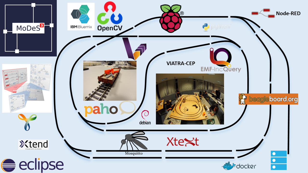
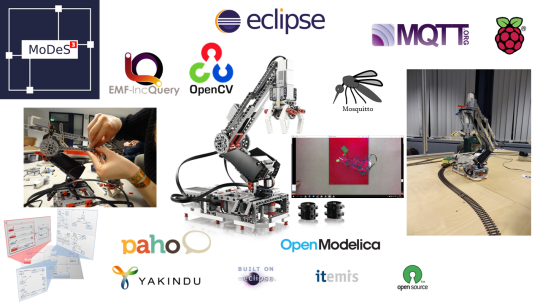
Here is a picture for a quick overview of the technologies we used.
During the developments, we have also contributed to the open-source world! Besides, all modules we implemented are open source and available in our GitHub repository.
For more details, read our blog!
The goal of our Eclipse IoT challenge project is to develop a robot arm which can execute tasks. This involves the integration of multiple information sources into a framework. Simulation is used to design and runtime analysis of the system. Computer vision is responsible to recognize the objects to be moved and also detect dangerous situation. The controller is designed with the help of statechart models and automated code generation provided the implementation. Various open-source IoT technologies provided the communication and integration between the components.
The result is a complex IoT application with many communicating components ensuring the execution of tasks related to the robot domain. Note that in this phase our robot executes only simple tasks however this architecture is easy to be configured to execute more complex missions too.
From the theoretical side, the most involved tasks were the following:
We have successfully implemented model-driven LEGO robot crane and summarize our research and engineering successes in the following points.
For an overview of related IoT technologies, see the picture below:
For a short demo, find the related post here!
For further details, please read our blog!