As the Lego robot arm executes a mission, information about the environment is required. Beside executing missions correctly, our goal is to detect any kind of danger caused by the robot. The goal is twofold: the robot has to know when to execute a mission i.e. the object to be moved is at the right place. Second, it has to stop when some dangerous situation happens, for example a human is present near to the robot.
We are building the monitoring infrastructure of the robot arm based on computer vision technologies. OpenCV helps us detecting and tracking the movements of the robot In case of a moving robot, no other moving objects should be there. In addition, computer vision will detect if the object to be transported is in the proper place to handle by the robot.
First time we built only a robot arm with limited functionality. According to the experiences, we have totally rebuilt it.
Rebuilding the robot was a big step forward for the project’s computer vision goals. Now, we are able to detect the orientation and also the movement of the arm, without markers.
The new concept is to put on some Lego element in a combination to form a larger component with distinctive shape and colour. The camera observes the whole loading area from the top, and searches for the elements.
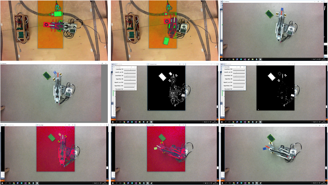
Using the same camera frames, we can detect the orientation of the gripper and find the cargos and the train.
For the gripper we needed a marker and that Lego element which we talked about before. The marker is directly connected to the gripper’s motor, so it is moving with the gripper during the rotation and other movements. The orientation is compared to the arm’s orientation so it won’t change during the movement of the arm, only the rotation influences its settings. The marker is a black circle, therefore we replaced the color detection with circle detection for this case.
Cargo has distinctive color.
In the following picture the output of the various steps of the process is depicted.

In the following we just sketch the working of the detection algorithms. Transforming the picture of the camera to HSV (Hue-Saturation-Value) representation. This will serve as a base representation for further processing. The next step is to decompose the picture according to the information we are looking for. In order to ease the tasks of the further processing, the picture is cut into pieces: The Lego arm, the gripper and also the object to be moved will be in different pieces of the picture.
Detecting the various objects of interest, we need to assess the color and the size of the objects in the picture: this is assessed at the next phase of the processing.
Edge detection algorithms search for the contour of the objects. Pattern matching algorithms try to find rectangles in the picture.
Numerical filters than used to sort the found objects (rectangles) according to their size. From the filtered objects, some special heuristics filter those object which are likely to be the searched object, namely the arm, the gripper and the load to be moved.
The movement of the arm is traced by reducing the problem to finding the moving rectangles in the filtered picture. Computing averages and tracing the middle point of the objects provide quite precise results.
So, as you might see, many algorithms work on the control and safety assurance of the Lego robot arm. Despite its complexity, it works well in practice!
