Before we start to talk anything about model railways, we need to understand how it works. But, because this article will be very long, I made a “read more” link right here – I apologise for the plus mouse-click, but it’ll be really long, really…
Analog and Digital Systems
Let me copy some text from Wikipedia here:
The earlier traditional analog systems where the speed and the direction of a train is controlled by adjusting the voltage on the track.
And another paragraph:
Digital model railway control systems are the modern alternative to control a layout and greatly simplify the wiring and add more flexibility in operations.
However, let’s go beyond wikipedia links 🙂
So, in the model railway “industry”, there are two solutions for controlling your trains: analog and digital controlling.
The analog systems are very simple: on each segment of the track you are able to adjust the voltage which empowers the trains, therefore this will affect their speed. For now you may have figured it out: if you want to stop a train, then you should set the voltage to zero on a segment where the train is moving. In this case, your train will stop, but because of the lack of power, there will be no other functions neither, like lamps on the locomotive, sound effects etc – this is kind of a deal-breaker in the eyes of an enthusiastic modeler.
So, the model railway industry was eager to find a solution, which keeps the opportunity to stop any train anywhere, but the functions mentioned earlier may remain still available. For that, every company developed digital systems for their locomotives, and with that move they ruined the joy of building it yourself – seriously, how could you enjoy it, if you have to be alerted which systems are compatible with each other? Bigger companies are adhered to their solutions (maybe until their death), so smaller companies have to work harder to cooperate with others.

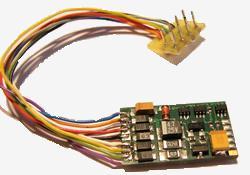
But we could say that all these systems are based on the concept of decoders – each train should have this little controller, a unit which controls the whole train: the engines, the lamps, the little speaker(s), anything you want (or anything you can buy). These decoders are continuously measuring the voltage of the tracks, listening for commands on them, and if one command is addressed to the decoder, the decoder will accomplish the task. With this solution, the whole layout should have connection to the control center, so there are no need for segments at all – or is it?
DCC signal
Start with another Wikipedia quote:
Digital Command Control (DCC) is a standard for a system to operate model railways digitally. When equipped with Digital Command Control, locomotives on the same electrical section of track can be independently controlled.
The voltage to the track is a bipolar DC signal. This results in a form of alternating current, but the DCC signal does not follow a sine wave. Instead, the command station quickly switches the direction of the DC voltage, resulting in a modulated pulse wave. The length of time the voltage is applied in each direction provides the method for encoding data.
I could not say it better, that’s what DCC is all about. We could control locomotives even if there are more than one on a segment, we could send numerous commands to it, we can stop it etc. It’s very promising for us.
But our concept for our model railway was a little different: we don’t want to interfere with this system. We want to build a totally separated system beside this and let that system to decide autonomously about dangerous situations and avoid accidents. That’s where the ABC mode came across.
ABC mode
The whole idea came from this site, where the authors explained why and how this method works. In short: the decoders have a feature that if they sense asymmetric signal in the tracks, a difference between the two polarity, then they could stop the train (if they were configured properly).
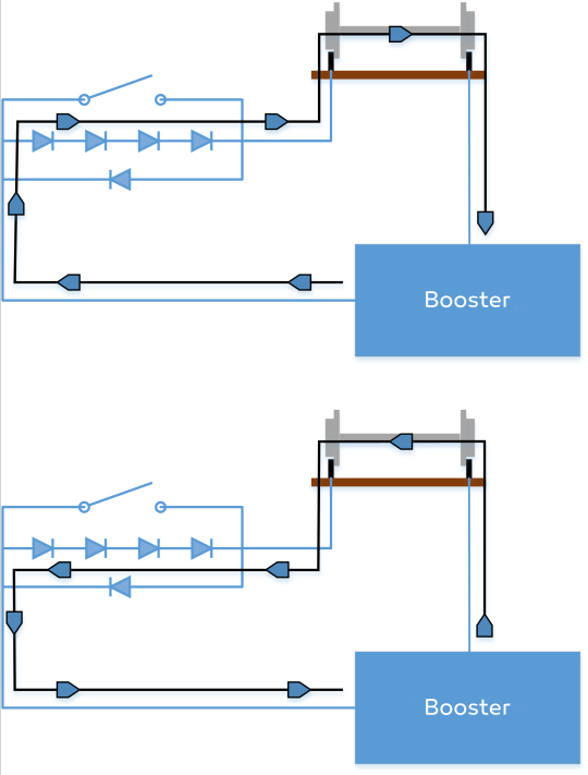
But how could we achieve this? It’s really simple: we need to develop a circuit just like this:

Let me explain: if the booster is “sending” the DC signal in one way, then the signal has to go through one diode, and that causes 0.7V drop on the voltage. When it changes the polarity and “sends” the DC signal on the other way, then the signal goes through 4 diodes which means 2.8V drop on the voltage. In this case, the decoder will sense the difference in the signal and will stop the train on the segment.
But, I don’t talked about the relay yet! That’s because the relay was open until now, so it’s not participating anyhow in the circuit. So, if we close the relay, than there is a “better” way for the signal by going through the relay without any voltage-drop, and let’s be honest: these signals like to go through the smallest resistance, so they “choose” this way. In this case, there will be no voltage-drop at all.
Conclusion
I have asked a question before:
Do we need segments at all?
The answer: yes, we do. With the segments of the track, we could create little circuits, connect them into the system, so we could stop trains on each segment without any lack of other functions – which is not that necessary for our project, but still, it’s nice to have lights on the rail.
zsoltmazlo
