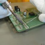
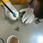
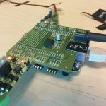
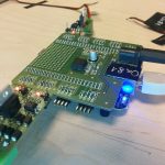
The bigger picture

Now, that the Open IoT Challenge is over, we have some spare time, therefore I try to explain for you how the hardware works and how was made. It won’t be a very long post, you shouldn’t read long paragraphs about electrons or voltage, but I will insert a tons of pictures into it, I should insert a read more link here. But trust me: it is worth watching them!

Superbeagles are on the road!

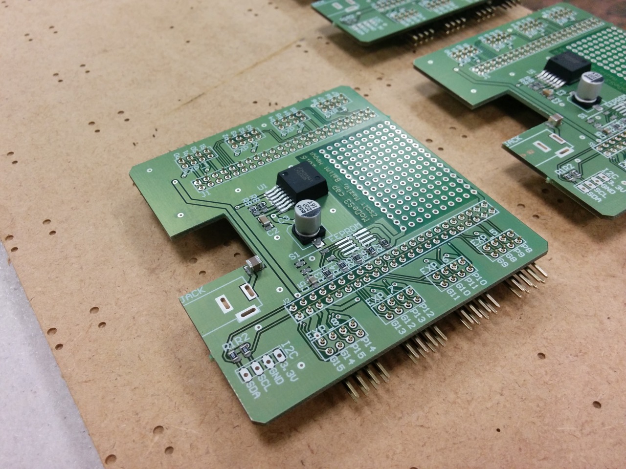
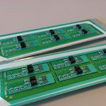
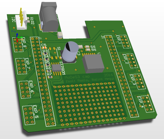
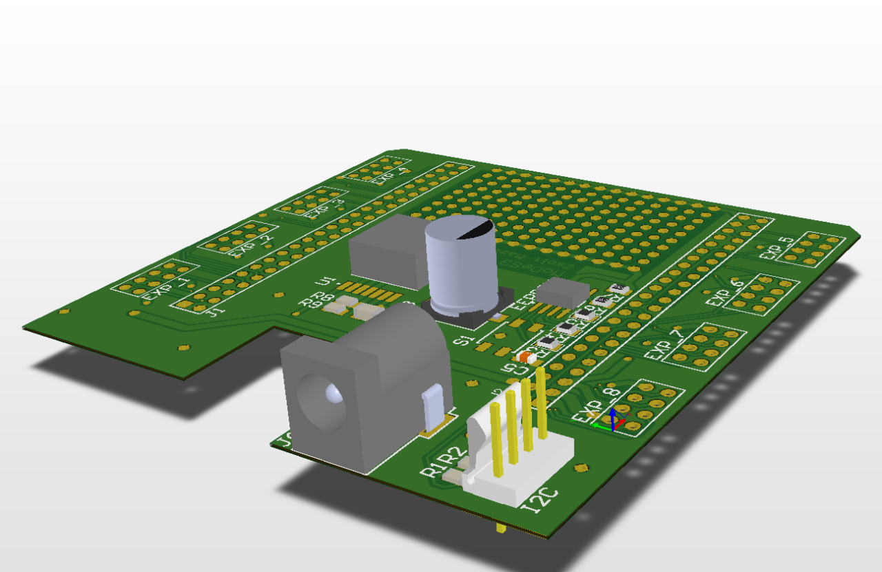
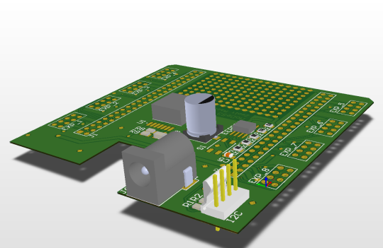
Previously one of my colleague, Bálint already wrote about why the Beaglebone Black board is so amazing, but in an other post I mentioned our little problem with the hardware – so I did managed to make a Cap for the beagle to make it Superman Superbeagle.

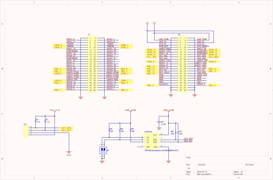
The design:
image

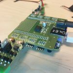
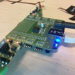
And the reality:

image

With this Cap, the Beaglebones could accept any power source between 7V and 20V, we have 8 pin headers to attach expander panels… oh wait, did I mentioned that we designed expanders also? No? My bad.

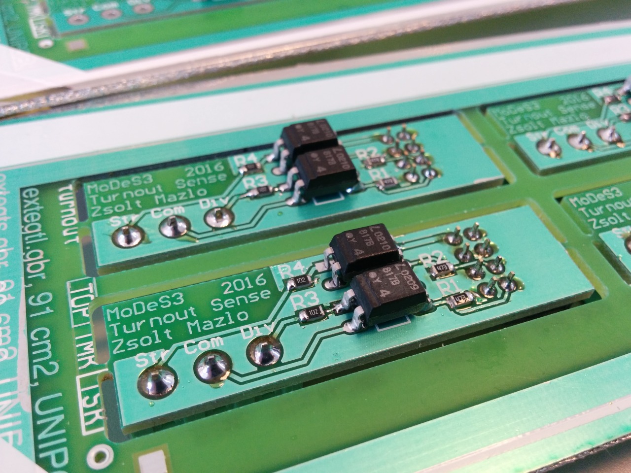
Not a rinse commercial: turnout sensation

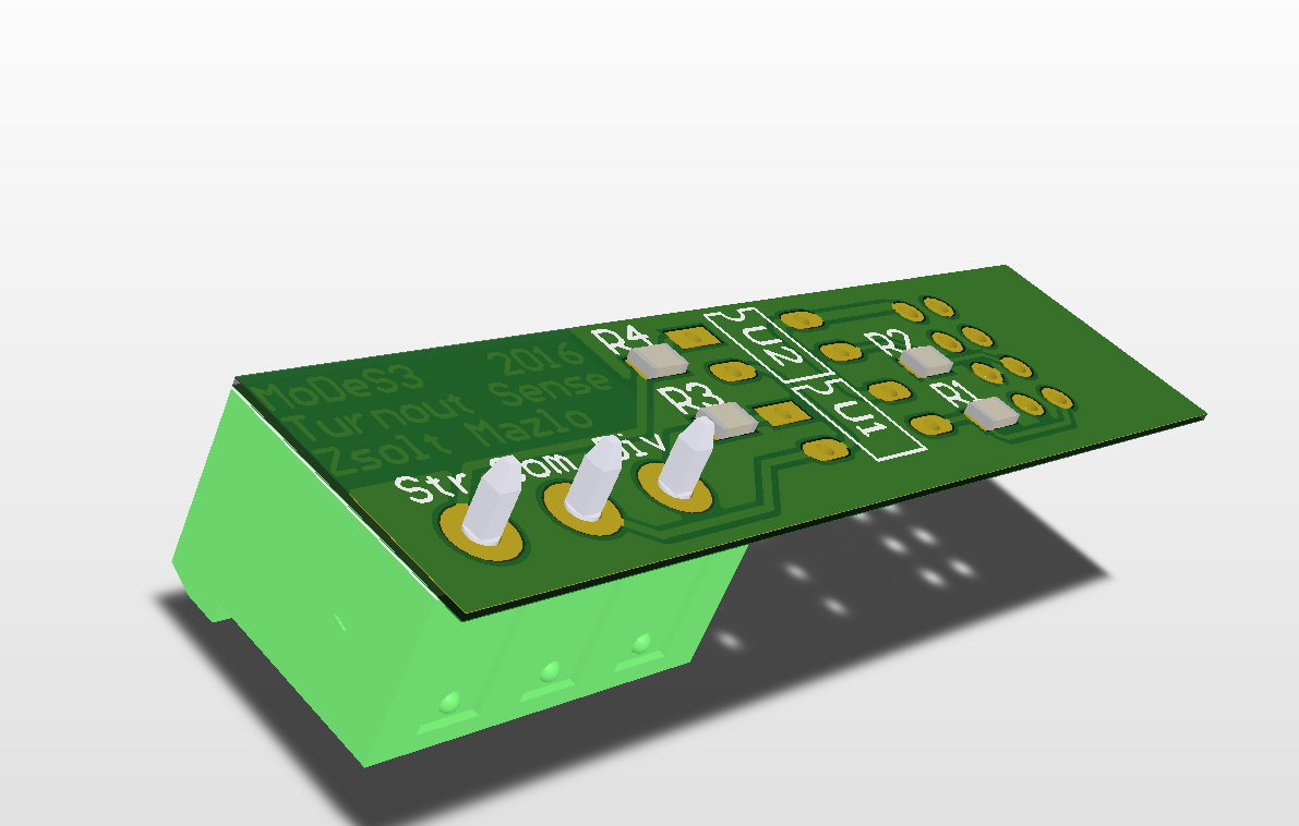
One of the many responsibility of the hardware is that it need to sense somehow the status of the turnouts. These informations are highly important: some cases, in which trains are moving towards each other, they could collide, so we should stop them; but if the turnout is in the right position, then we could pass one of them through the turnout and even avoid the collision. With this knowledge, we could make the movement of the trains continuously beside the safe operation.

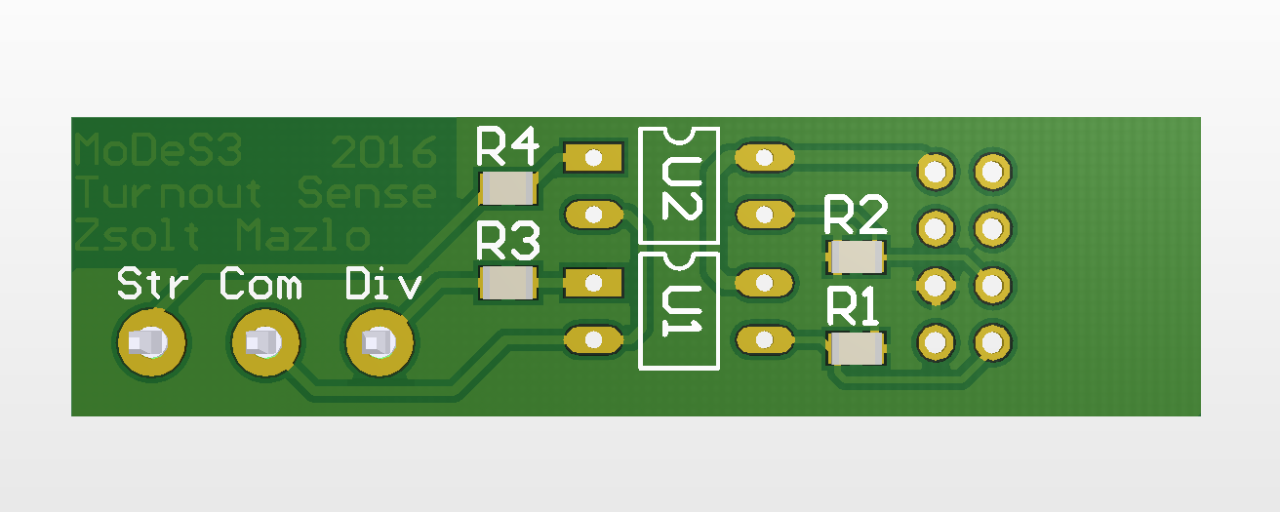
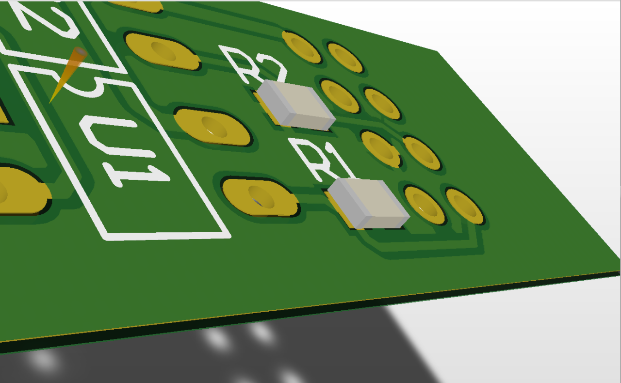
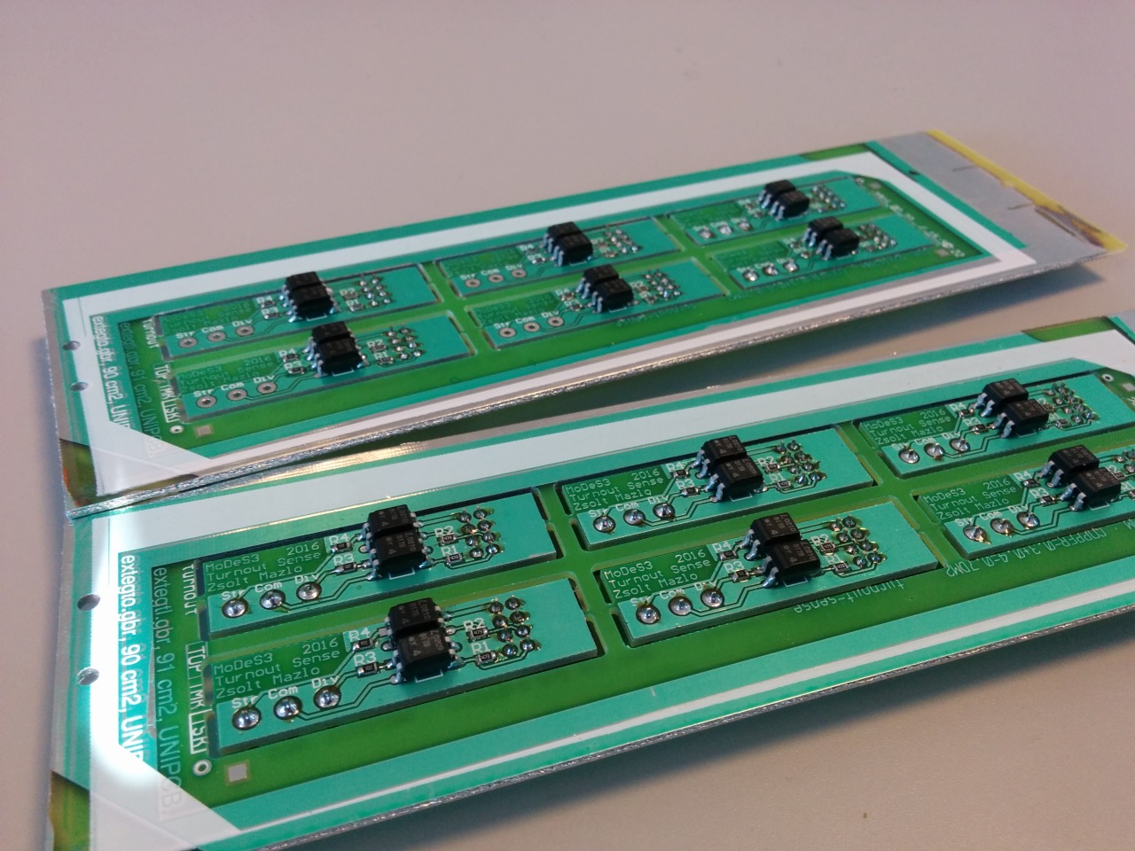
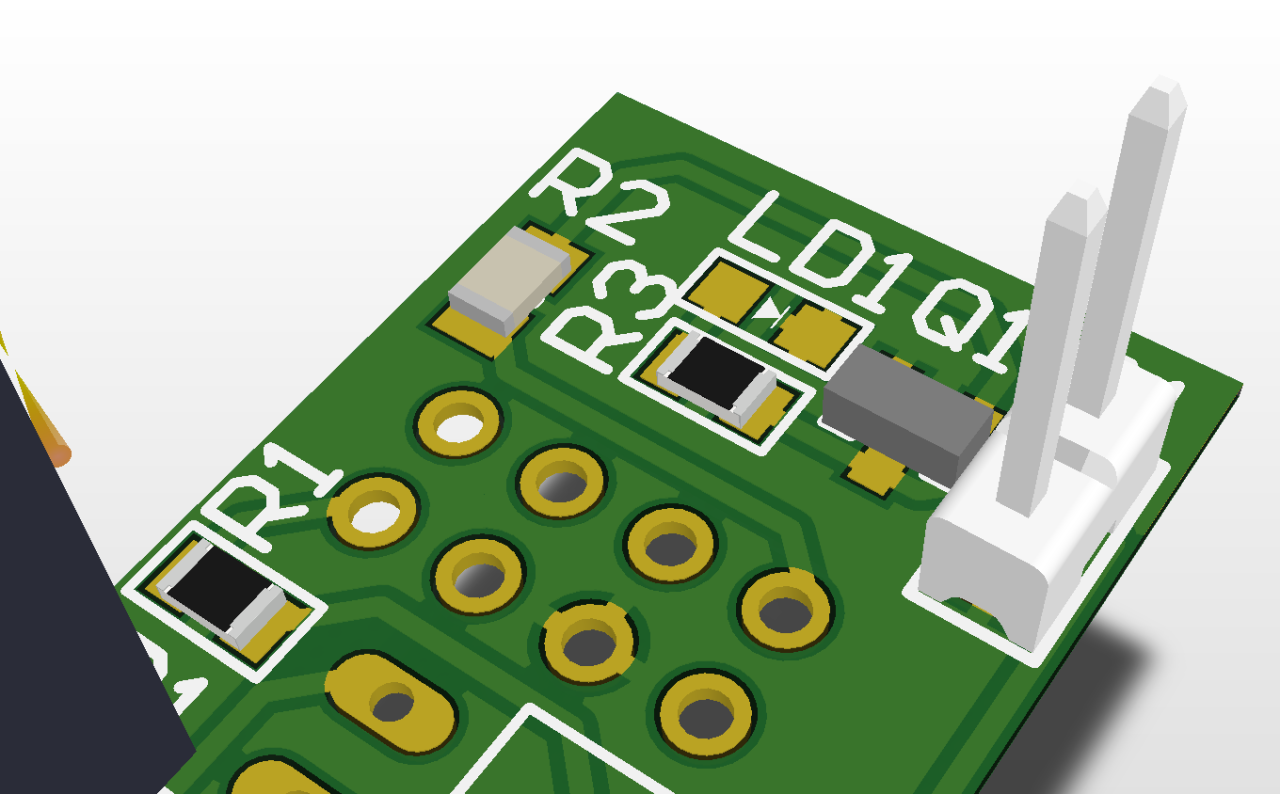
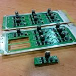
Therefore we made some measurements about how the turnout actuators are work and after that we created a PCB to handle this.

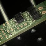
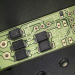
Here is the design:
imageimageimage

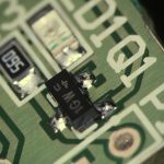
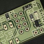
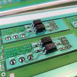
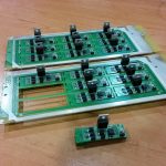
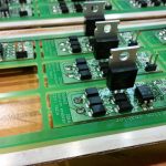
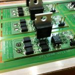
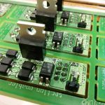
And the reality:

imageimage

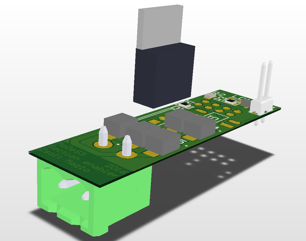
Section enablers

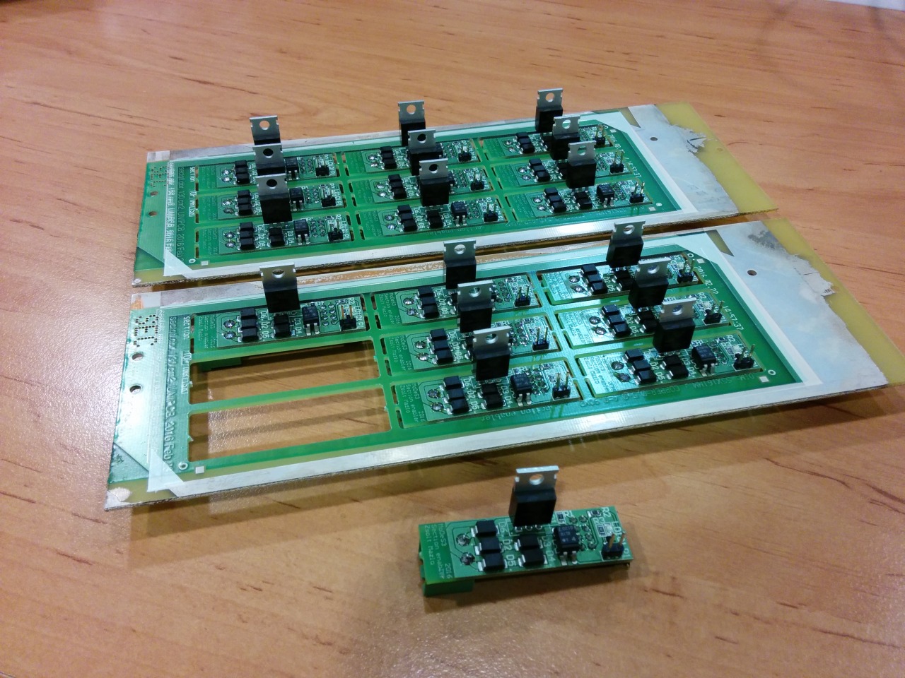
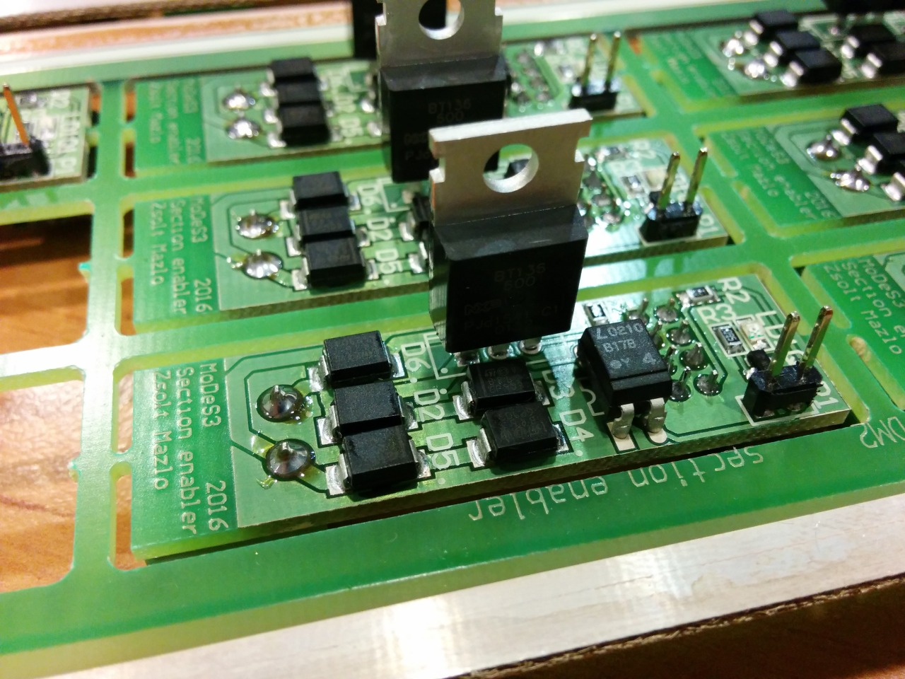
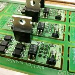
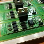
Okay, let assume that we are getting every information about the track that we need: the location of the trains, the turnouts’ status, and so on, and one time, we need to stop one train: but how, you may ask. That’s the reason why we designed and assembled the section enabler or disabler PCBs: in the near past I wrote about the mechanism.

Design:
imageimage

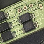
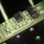
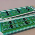
Reality:
imageimage

Designing the PCB for Beaglebone Black

In the previous entries, we already talked about that we would use Beaglebone Black units to run our safety logic, but in my opinion, these systems have a problem: they could work only if you provide them 5V power source. Of course it’s not that big problem if you are starting a new project based on these computers, because you could choose your power source as you want.
But in our case, we already had a 12V power source under the hood. Furthermore we should use 12V source to feed railway lights, so we had to find out a solution. In one of my previous entries I already made a prototype, which would do the trick for us. But we need to install this solution somehow on the Beaglebone, so this weekend I designed a PCB (printed circuit board) to place this solution. 

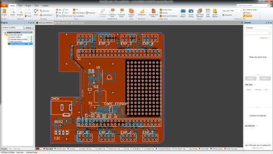
Here is the final version:  

image

Disclaimer: I may call it final version, but every evening I find something to modify. So this is maybe not the final version, but it will have no major modification in the near future.

First try, first failure

At the beginning, I started to design our board with Eagle: this program is a lightweight designer for PCBs, and it’s lovable for its multiplatform quality, so it was perfect for me. But I merely started to design anything, one problem came after another. The biggest of all, I couldn’t find any libraries which would give the footprint of our chosen power module, the TI LMZ22005.

Intermezzo: we chose this module because it’s super easy to install on any design. You should only use some capacitors and resistors, and you are done (not to mention, the values of these elements are also provided by TI).

So, I had to make a decision: shall I go on with eagle and design the footprint of the power module myself, which hold the danger of faulty design, or choose another program and learn how to use it. Bálint pointed out that he heard good reviews about the Altium Circuit Maker program, and after a short test, we decided we should give it a try.

Can I invite you for a cup of coffee?

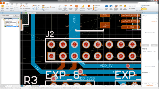
If you are starting to use a new software, first it’ll be totally unfamiliar for you. So you should learn how it works, how can you accomplish what you want, etc. For PCB designer applications, it’s more difficult: they have great set of functionality, tremendous preferences. That’s why for the first couple of hours I had to work as “we were just getting to know each other”.

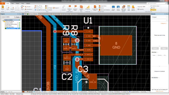
image

But in the end, I managed to design the circuit. I chose every elements of it (it’s a big help that you have oodles parts from Octopart which you could use), I “just” had to route the PCB itself.

The routing

So, after the logical design, you have to place every element on the board and figure it out how you should make connections between them – that’s the routing. For a senior PCB designer, it’s not that hard to do, but for me, who had no experience at all in making PCBs and in the program also, I had my lesson.

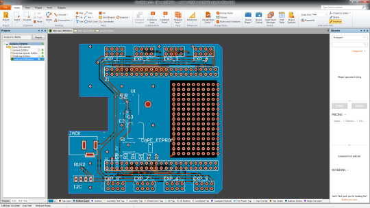
image

This work was all about patience: routing every single wire to the right place was not that hard, just time-killing, because measuring distances, the calculating and designing the perfect layout was hard. Not because of the math: if you do something wrong the board would be useless, you have to fix the problems and print it out again, but it costs a lot of money, so you kind of have only one shot. In the consciousness of this I took my time and measured everything twice, rethought anything at least once and I pursued the perfect solution.

image

Everything that has a beginning has an end

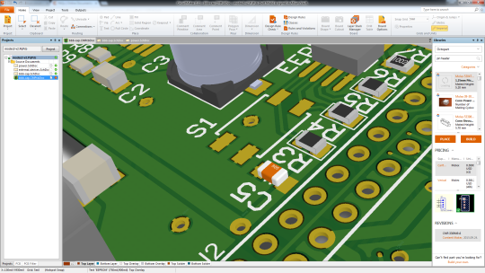
After finishing it, I talked to people who had more experience in designing, took their pieces of advice, and now I am waiting for the bid and I am hoping that it will not take us into bankruptcy.

image
image
image
image