A little history lesson

Before we start to talk anything about model railways, we need to understand how it works. But, because this article will be very long, I made a “read more” link right here – I apologise for the plus mouse-click, but it’ll be really long, really…

Analog and Digital Systems

Let me copy some text from Wikipedia here:

The earlier traditional analog systems where the speed and the direction of a train is controlled by adjusting the voltage on the track.

And another paragraph:

Digital model railway control systems are the modern alternative to control a layout and greatly simplify the wiring and add more flexibility in operations.

However, let’s go beyond wikipedia links 🙂

So, in the model railway “industry”, there are two solutions for controlling your trains: analog and digital controlling.

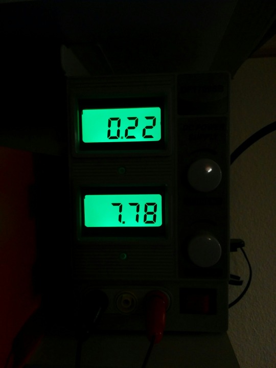
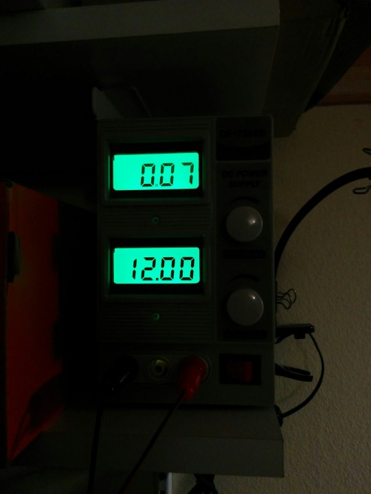
The analog systems are very simple: on each segment of the track you are able to adjust the voltage which empowers the trains, therefore this will affect their speed. For now you may have figured it out: if you want to stop a train, then you should set the voltage to zero on a segment where the train is moving. In this case, your train will stop, but because of the lack of power, there will be no other functions neither, like lamps on the locomotive, sound effects etc – this is kind of a deal-breaker in the eyes of an enthusiastic modeler.

So, the model railway industry was eager to find a solution, which keeps the opportunity to stop any train anywhere, but the functions mentioned earlier may remain still available. For that, every company developed digital systems for their locomotives, and with that move they ruined the joy of building it yourself – seriously, how could you enjoy it, if you have to be alerted which systems are compatible with each other? Bigger companies are adhered to their solutions (maybe until their death), so smaller companies have to work harder to cooperate with others.

image

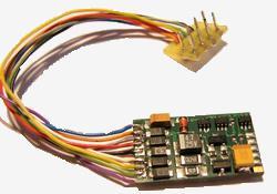
But we could say that all these systems are based on the concept of decoders – each train should have this little controller, a unit which controls the whole train: the engines, the lamps, the little speaker(s), anything you want (or anything you can buy). These decoders are continuously measuring the voltage of the tracks, listening for commands on them, and if one command is addressed to the decoder, the decoder will accomplish the task. With this solution, the whole layout should have connection to the control center, so there are no need for segments at all – or is it?

DCC signal

Start with another Wikipedia quote:

Digital Command Control (DCC) is a standard for a system to operate model railways digitally. When equipped with Digital Command Control, locomotives on the same electrical section of track can be independently controlled.

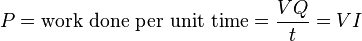
The voltage to the track is a bipolar DC signal. This results in a form of alternating current, but the DCC signal does not follow a sine wave. Instead, the command station quickly switches the direction of the DC voltage, resulting in a modulated pulse wave. The length of time the voltage is applied in each direction provides the method for encoding data.


I could not say it better, that’s what DCC is all about. We could control locomotives even if there are more than one on a segment, we could send numerous commands to it, we can stop it etc. It’s very promising for us.

But our concept for our model railway was a little different: we don’t want to interfere with this system. We want to build a totally separated system beside this and let that system to decide autonomously about dangerous situations and avoid accidents. That’s where the ABC mode came across.

ABC mode

The whole idea came from this site, where the authors explained why and how this method works. In short: the decoders have a feature that if they sense asymmetric signal in the tracks, a difference between the two polarity, then they could stop the train (if they were configured properly).

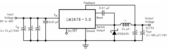
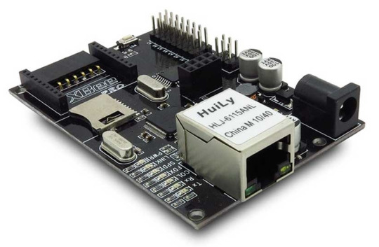
But how could we achieve this? It’s really simple: we need to develop a circuit just like this:

image

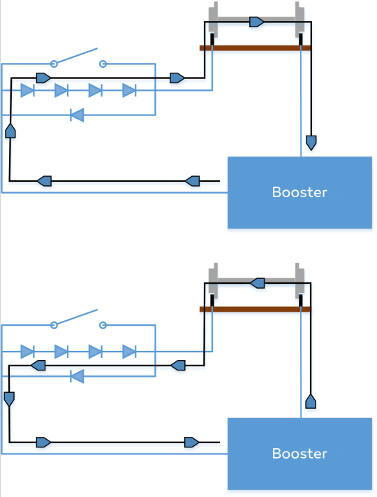
Let me explain: if the booster is “sending” the DC signal in one way, then the signal has to go through one diode, and that causes 0.7V drop on the voltage. When it changes the polarity and “sends” the DC signal on the other way, then the signal goes through 4 diodes which means 2.8V drop on the voltage. In this case, the decoder will sense the difference in the signal and will stop the train on the segment.

But, I don’t talked about the relay yet! That’s because the relay was open until now, so it’s not participating anyhow in the circuit. So, if we close the relay, than there is a “better” way for the signal by going through the relay without any voltage-drop, and let’s be honest: these signals like to go through the smallest resistance, so they “choose” this way. In this case, there will be no voltage-drop at all.

Conclusion

I have asked a question before:

Do we need segments at all?

The answer: yes, we do. With the segments of the track, we could create little circuits, connect them into the system, so we could stop trains on each segment without any lack of other functions – which is not that necessary for our project, but still, it’s nice to have lights on the rail.

zsoltmazlo

Great invention: the buck converters!

Today I worked on the hardware stuff and I managed to build this circuit:

image

And the result is:

image

But what is this and why do we need it? Or, do we need it at all? Keep reading, and you will find the answers for all these questions!

Buck converters

In our future plans the layout will have some signaling lamps beside the tracks, and these signals need 12V to operate. But our chosen embedded systems, the BeagleBone Black cards need only 5V. Therefore, if we want only one power source which feeds all these devices, then we need to scale down
12V to 5V somehow.

Intermezzo: why would we use only one power source? It’s really simple: it makes the wiring simpler, there will be no more power sources and power lines, and the power loss on the wires will be no harm for us. Furthermore, it makes the future maintenance lot more easier.

With linear voltage regulators this would waste 7V on heat, and that means we will have efficiency of ~41%. Just waste of energy!

About 6 months earlier, I’ve started searching on Youtube for channels working with electronics, and I must admit that the whole idea came from this video:

So buck converters do a little magic trick: they get an input
voltage and they transform it up or down to higher or lower voltage –
with really high efficiency (about 90%). This is a very good news for us,
because that’s what we want and we can’t find a better solution for this purpose!

Some measurements – only for the hardcore readers

So, after I put the layout together I made some measurements. First, I connected the BeagleBone card to my power supply directly without any buck converters. That’s what I measured:

image

In this case it’s clear, that the output voltage is 4.99V and the card consums 310mA.

Then I added our new prototype as you can see in the following picture:

image

On the image you can see that the BeagleBone is connected to the output of the buck converter, and the buck converter is connected to the power supply by the black and red hook. Then I started to turn up the voltage on the power supply:

image

At 7,78V the current consumption is started to decrease…

image

And that’s what I am talking about! If we supply our card from 12V, it consumes only 70mA, only 22% of the original consumption!

Do the math (don’t hate me)

First, let’s Google the definition of Electric power:

The electric power in watts produced by an electric current I consisting of a charge of Q coulombs every t seconds passing through an electric potential (voltage) difference of V is:

image

Then some calculation:

  1. If consumption is 0.3A on 5V, our system will consume 0,3A*5V=1.5W power on each BeagleBone card.
  2. but, if it consumes only 0.07A on 12V, then the power consumption is 0.07A*12V=0.84W.

This is 45% more efficient than the other solution, and we just saved 0.66W power on each BeagleBone. That’s where I became so happy that I started to write this entry, so… the story ends here. Thanks for your attention, I hope you found this entry useful!

zsoltmazlo

What this project was all about

Before we start to post videos, photos and other stuff about this project, I may say something about this project’s history.

It started back in 2014, when we jumped into a project to desing embedded systems and a model railway demonstrator. So with one of our member, Benedek, we started to build something. We literally had no experience with embedded systems neither with model railways, so the first attempt to create this system – let’s be honest – failed. We wanted to use model based techniques for the development, but we were not able to upload any complex, generated code to the system, which was based on Arduino Ethernet boards. We could only use hand-written code with small complexity.

Intermezzo: why we choose Arduino for the first place? Because I was the one who had some experience with embedded systems, and I only knew Arduino, and needles to say, I was convinced that it would do the work.

Furthermore, these units (like one on the picture) were so customized ones that even uploading code was a disaster – I don’t know what we did wrong, but our serial-converters which needed to upload the code were starting to die after a short time of usage.

But, either way we managed to implement an interface for the layout to be able to stop trains. We could read from the layout where the trains were, but nothing more. So our safety logic was a bit harsh with the trains – they had to be stopped a lot. This was the time when we realized that we need the proper hardware for this project. And then we could speak about any further developments.

Researchers’ Night (Kutatók éjszakája in Hungarian)

But, we worked a lot, we had some results in the field, so we went to the Researchers’ Night to present the system. There we showed this small and stupid system to people, we talked about it, showed it to kids and adults and tried to brought them closer to IT. And grab their attention.

image

It was a huge success, I think I could say that they loved it (especially the kids). We were really happy with the feedbacks, so we decided to enhance our system, change the components and the software and to build a completely new sytem on top of the former experiences.

And that’s where the IoT Challenge came across.

Because when we heard about this challenge we decided – we are getting back to square one, start to redesign everything (beside the track), start to make better plans, make more research about embedded systems, modern techniques and make a project which could be really used to demonstrate the model based development of complex systems.

zsoltmazlo

The past and the future of the hardware – Part 1

In the following, I will overview the past and the future of the hardware we use in the project!

At the post “What this project was all about”, zsoltmazlo described the application of Arduino boards. The choice was based on the experience of easy usage of the libraries, but later during the development of the models it turned out that they hit their limitations.

As you may know, the Arduinos are basically microcontrollers. They are really an all in one package. But with microcontrollers, the programmer is facing very serious limitations. The Atmel ATmega328P has 32 Kbytes of program memory, and 2 Kbytes of data memory, with a 20 MHz operating frequency. This is the processor on the well famous Arduino Uno, and we also had Ethernet capable board. But the memory limitations are serious.

image

Comparing this with even your smartphone: just lack of performance. However, we have to mention, that although they look quite weak, they are very usable. 98 percent of the computers are used in embedded systems, and most of them utilizes microcontrollers like the one I mentioned.

Well, than what was the problem? We develop in a model-based fashion. With a safety critical system, you can’t just write code, and hope it just works, or test it to a level where the developer thinks it’s safe enough. You need mathematical proofs of the correctness of your solution, and you can do it with model based developement. You create some abstract representation of your application with statecharts, flow diagrams, or other abstract representations (read the post “Statecharts are everywhere!” if you are interested). These are mathematically more representable objects, therefore we can analyze this.

So what is the bottom line? When you are ready with analyzing the correctness of your model, you somehow need to make this model runnable. From a model, you can generate code (e.g C, C++, Java, etc.), so you can compile and run it. The problem with these code generators is that they are not prepared for the limitations of an embedded system: generated code is used to use dynamic memory handling, and trash a little. So little, you wouldn’t notice this in a PC, but with 2K RAM, you will, and the application will crash because it can’t allocate more memory for itself.

It turned out that to overcome these difficulties might be much harder than upgrading our hardware to the next level, so we chose the latter, and started developing the new hardware to suit our needs. Sure, we could work out how we could generate code to fit inside, but the MoDeS3 project isn’t about just us. It’s a tool to develop safe and smart applications, and the hardware needs may be varying between projects, so it is just better to fit the future needs.

Coming up: the new hardware and the horizon is opened for us!

Bálint