Integrating model railways with IBM Bluemix and Node-RED

Cyber-Physical Systems (CPS) are on one hand close to embedded systems as they are also built from sensors, controllers and actuators, where the sensors gather heterogeneous information from the environment, the controllers observe the gathered information and order the actuator to modify the environment according to the observed information. On the other hand, CPS systems are aiming to harvest the benefits of elastic cloud based resources to provide more sophisticated automation services.

As part of the MoDeS3 project we successfully integrated the safety logic that controls our model railways, with IBM Bluemix and Node-RED.

IBM Bluemix

Bluemix is an open standards, cloud platform for building, running, and managing apps and services. Bluemix is designed to make developers’ lives easier. That’s why it provides developer teams of all sizes with the flexibility to scale compute power at a very granular level, seamlessly collaborate on source code and shared APIs, and manage apps’ performance, logs and costs from a single dashboard.

Bluemix has three open source compute options to power your applications:

  • Cloud Foundry: Cloud Foundry is an open source PaaS that offers devs the ability to quickly compose their apps without worrying about the underlying infrastructure. Bluemix extends Cloud Foundry with a number of managed runtimes and services, enterprise-grade DevOps tooling, and a seamless overall developer experience.
  • IBM Containers: IBM Containers allow portability and consistency regardless of where they are run—be it on bare metal servers in Bluemix, your company’s data center, or on your laptop. Easily spin up images from our public hub or your own private registry.
  • VMs: Virtual machines offer the most control over your apps and middleware. Bluemix uses industry-leading OpenStack software to run and manage VMs in a public cloud, a dedicated cloud, or your own on-premises cloud. Key OpenStack services such as Auto Scaling, Load Balancing, and Object Storage can be used in conjunction with Bluemix services to build and run hybrid apps.

Source of information: IBM Bluemix homepage


Node-RED

Node-RED is a tool for wiring together hardware devices, APIs and online services in new and interesting ways. It provides a browser-based flow editor that makes it easy to wire together flows using the wide range nodes in the palette. Flows can be then deployed to the runtime in a single-click.With over 225,000 modules in Node’s package repository, it is easy to extend the range of palette nodes to add new capabilities.

The light-weight runtime is built on Node.js, taking full advantage of its event-driven, non-blocking model. This makes it ideal to run at the edge of the network on low-cost hardware such as the Raspberry Pi as well as in the cloud.

Source of information: Node-RED homepage


How were model railways integrated with the cloud?

As we describer earlier in a blogpost we designed the model railway control logic, also known as safety logic, with YAKINDU Statechart Tools. YAKINDU Statecharts enabled automatic code generation from the designed statecharts. This way we could directly create the implementation of the safety logic, based on statechart semantics.

However, generating codes automatically were not enough. We had to integrate custom Java codes to the generated codes through an interface. In this way we could connect the statecharts with the physical model railway track, including the BeagleBone Black based embedded controllers.

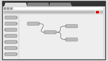
After that as an experiment we designed the communication module, originally implemented in Java and that is neccessary for communication between the statecharts, in Node-RED. The high-level signals used in the communication have been constructed as flows in Node-RED, depicted on the following figure.

As you can see, although different requests, originating from the left-hand side, has different flows containing some functions, they all end in the same response node. It was in order to make the design easier and less redundant, excluding the status and error logging nodes used for debug purposes.

So, as you may have already guessed the Node-RED flows and the generated statechart codes have been deployed into IBM Bluemix. Each turnout has its own statechart and they run separately, connected through the Node-RED flow, to make the communication easier and use cutting-edge Internet of Things technolgy!

We deployed each component (statecharts that control the turnouts and their nearby sections, and the communication module designed in Node-RED) into the IBM Bluemix as a container. Six containers were running the generated Java codes, each in its own, and the seventh container was deploying the Node-RED flow. They were put in the same subnetwork, so all the statecharts could communicate with the Node-RED flow as described above.

On a local machine working at the Fault Tolerant Systems Research Group at  BME, only a proxy module was running that received signals from the YAKINDU statecharts to stop the trains if neccessary. This module periodically transmitted status about the track to the cloud, so the statecharts could make decisions based on the real-world sensor information.


Conclusions

Although deploying a safety-critical system into the cloud is strongly opposed, due to network latencies, nondeterministic instabilities of the cloud, noisy neighbours in the virtual machines running in the cloud, etc, it was an interesting experimentation. It was fascinating to see that the section in danger, where the trains could collide, was disabled from the cloud. Despite we did not know where the containers were running exactly in the cloud (e.g. in the EU/USA/Asia), the network latency was low enough not to have serious implications in our case.

We were more than satisfied with the avilability and the stability of IBM Bluemix, so we strongly recommend to give it a try. It has a strong community which is eager to help you if you have any difficulties with the cloud services offer by IBM.

Last but not least, we would like to recommend Node-RED as well. If you are either a Java Script developer, or you would like to connect your embedded systems together, you may find it really useful.

Delivered in cooperation with Daniel.

Statecharts are everywhere! #5 – Validation example

As we mentioned in a former post, Bence, who is our colleague, has extended the validation rules embedded into YAKINDU Statechart Tools with new ones. The high-level purposes of the validation rules are to reduce the ambiguity and nondeterminism of the design models and to avoid bad design practises and structures.

Let’s see how it works in practise.

Let’s image we designed a statechart, that contains a composite state with two parallel regions as depicted on the next figure. Each region has two states, which are connected through transitions. Although most triggers are different in the two regions, there is a trigger, called Protocol.response, that is the same for both regions. Although these two transitions have the same trigger (Protocol.response) the respective actions are different: in the first first region Protocol.actionA, in the other region Protocol.actionB is the respective action. Since the execution order of transitions with the same trigger in parallel regions is undefined, it is a bad design pattern (so called antipattern).

Bence designed an EMF-IncQuery validation pattern to automatically recognize these kinds of design patterns. More on EMF-IncQuery validation patterns can be read in the respective blogpost here.

As the validation rules are evaluated incrementally by the EMF-IncQuery Validation Framework, warnings are showed in the Problems view of Eclipse. If we double click on a warning message, it automatically jumps to the respective model element, to help correct the error easily.

Statecharts are everywhere! #4 – Validation & Verification

In the previous parts of Statecharts are everywhere series we discussed a lot of things. First, we talked about what xtUML BridgePoint Editor is, and how we designed the ‘safety logic’ with it. Second, we talked about the reasons why we switched from BridgePoint to YAKINDU Statechart Tools (SCT). Third, we introduced YAKINDU Statechart Tools.

Now, we are going to talk about the validation features delivered with SCT, and our extensions: validation based on incremental graph matching, and verification based on timed automaton formalism.

YAKINDU Statechart Tools (SCT) comes with a Validation framework that ensures the detection of unreachable states, dead ends and references to unknown events. These validation constraints are checked live during editing [1].

Xtext

This framework is based on the Xtext’s Validation features that provide both syntactical and semantical validation. The syntactical correctness of any textual input is validated automatically by the parser and any broken cross-references can be checked generically [2]

Semantical validation means the developer of the grammar (that can be either textual, or graphical) can write validation rules in Java language for model elements. These rules are applied on the model and if they are not justified, then an error message is shown in the editor. More on validation can be read in the documentation of Xtext.

This way it can be ensured, that the model is valid, because it meets the well-formedness constraints it was set against.

Built-in validation rules

After the introduction, let us see, what validation rules are built in SCT [3]. They mostly inherit from the semantics of (UML) statecharts, that is a well researched area.

  1. A state must have a name.
  2. Node is not reachable.
  3. A final state should have no outgoing transition.
  4. A state should have at least one outgoing transition.
  5. Initial entry should have no incoming transition.
  6. Initial entry should have a single outgoing transition
  7. Entries must not have more than one outgoing transition
  8. Outgoing transitions from entries can not have a trigger or guard.
  9. Outgoing transitions from entries can only target to sibling or inner states.
  10. Exit node should have no outgoing transition.
  11. Exit node should have at least one incoming transition
  12. Exit node in top level region not supported – use final states instead.
  13. A choice must have at least one outgoing transition.
  14. The region can’t be entered using the shallow history. Add a default entry node.
  15. The region can’t be entered using the shallow history. Add a transition from default entry to a state.
  16. The source / target states of a synchronization must be orthogonal.
  17. The source / target states of a synchronization have to be contained in the same parent state within different regions.

Some other rules that are applied on the SCT model as well [4], but they do not necessarily come from the statechart semantics.

  1. A choice should have at least one outgoing default transition.
  2. In/Out declarations are not allowed in internal scope.
  3. Local declarations are not allowed in interface scope.
  4. The evaluation result of a time expression must be of type integer.
  5. The evaluation result of a guard expression must be of type boolean.
  6. Target state has regions without ‘default’ entries.
  7. Region must have a ‘default’ entry.
  8. The named entry is not used by incoming transitions.
  9. The named exit is not used by outgoing transitions.
  10. The parent composite state has no ‘default’ exit transition.
  11. The left-hand side of an assignment must be a variable.
  12. Missing trigger. Transisition is never taken. Use ‘oncycle’ or ‘always’ instead.

EMF IncQuery

Bence, who is a friend of ours has extended the validation rules mentioned before with new ones. But these rules were composed using EMF IncQuery and are applied by its Validation Framework, rather than the Xtext Validation Framework.

EMF-IncQuery is a framework for defining declarative graph queries over EMF models, and executing them efficiently without manual coding in an imperative programming language such as Java.

With EMF-IncQuery, you can:

More on the EMF IncQuery Validation Framework can be read in its documentation.

EMF-IncQuery Validation Framework

image

Bence composed new validation rules in the IncQuery’s declarative query specification laguage. These rules are applied on the statechart model. If a rule is violated by the referred model then an error message is displayed next to it.

So how is IncQuery supposed to be used for validation? We are going to show you in an example.

image

The first pattern is responsible for returning declared events that are not used in the state machine. The validation message is defined by the Constraint annotation above the first pattern. The second pattern is an auxiliary pattern.

First of all, let us talk about how to define IncQuery patterns. Let us take a look at the first pattern. Note, that the pattern name must be preceded by the „pattern” keyword. Between parantheses we must declare what nodes of the instance model we want access to. Naturally, the given name must appear in the pattern body and refer to a node type.

„Event : EventDefinition” says that we will want access to the nodes that we refer to as „event” in the pattern body and they are instances of „EventDefinition”. Then, the pattern body must be constructed. Each line states something about the result set. „EventDefinition(event);” states, that through „event” we only want to refer to nodes that are instances of „EventDefinition”. Patterns can be reused with the „find” keyword. This can be imagined as a function call: all of the statements of the called pattern will be applied in the pattern we call it from. To invert the meaning of the find keyword it must be preceded by the „neg” modifier. It forbids the match of the called pattern with the given parameterization.

In the second pattern we want to return nodes, instances of„EventDefinition”, that are not referred by any instance of „FeatureCall” or „ElementReferenceExpression”. FeatureCall.feature(_featureCall, event);” states that there must be a „FeatureCall” instance that has a „feature” reference to „event” (which is as stated before is an instance of EventDefinition). The statements are in a logical AND relation. As you can see, OR relation can be declared as well using the „or” keyword.

To mark the unused events for the Yakindu user a Constraint annotation must be defined. In the annotation the target editor, the message and the severity must be given apart from the elements that we want to mark. The elements are returned by the pattern the annotation is bound to.

New validation rules

The high-level purposes of the validation rules are to reduce the ambiguity and nondeterminism of the design models and to avoid bad design practises and structures.

  1. The transition has the same trigger as another transition in the parallel region, but different action.
  2. This transition is in a circle of always triggered transition causing a livelock.
  3. Ambiguity. This transition is not the only default transition of the exit event.
  4. The transition has the same trigger as another transition, which is on a higher level in the state hierarchy.
  5. Same trigger used on outgoing transitions.
  6. The transition is covered by an always triggered transition.
  7. This choice should have at least two outgoing transitions.
  8. This final state should have no outgoing transition.
  9. This exit should have no outgoing transition.
  10. This entry should have no incoming transition.
  11. This entry has more than one outgoing transition.
  12. Missing trigger. Transition is never taken. Use ‘always’ instead.
  13. This region has no entry node.
  14. This region has more than one entry node.
  15. Unreachable vertex.
  16. Unused variable.
  17. Unused event.

Verification

Verification is used for making sure the designed system meets its requirements, and work as we imagined. Although there are a lot of verification techniques, we use timed automaton formalism and computational tree logic.

UPPAAL

We chose timed automaton formalism because it is similar to the formal operation of YAKINDU statecharts (in theory), and we already have practise with UPPAAL. UPPAAL is an industry-wide known tool for formal verification of real-timed systems by timed automata.

UPPAAL uses a subset of Computational Tree Logic (CTL for short). The UPPAAL query language consists of a path formula quantified over none, one, more or all paths of the model. Specifications used in UPPAAL can be classified into reachability, safety and liveness properties. Next figure illustrates the formulae supported by UPPAAL. Filled circles represent those states for which a given state formulae hold.

image

Model transformation

Besides the validation rules, Bence developed a model transformation plugin for Yakindu as well. The plugin transforms a chosen SCT model into a timed automaton, and automatically generates CTL expressions for formal verification.

The model transformation plugin is continuously evolving to support all features (e.g. choice, entry, exit nodes, parallel regions, etc) of statecharts.

As an example the design and formal models of main region of Section statechart is depicted in the next figures.

Design model:

image

Formal model:

image

Finally, the formal verification result of the timed automata transformed from the Section statechart is depicted in the next figure.

image

Statecharts are everywhere! #3 – Getting started with YAKINDU Statechart Tools

After leaving BridgePoint, it was time to get started with YAKINDU Statechart Tools. Let’s start with an official introduction of YAKINDU Statechart Tools from its website:

The free to use, open source toolkit YAKINDU Statechart Tools (SCT) provides an integrated modeling environment for the specification and development of reactive, event-driven systems based on the concept of statecharts.

Following figures are from the website of YAKINDU Statechart Tool.

Editing

SCT features an intuitive combination of graphical and textual notation. While states, transitions and state hierarchies are graphical elements, all declarations and actions are specified using a textual notation. The usability of the statechart editor is simply fascinating.

Validation

The validation of state machines includes syntax and semantic checks of the full model. Examples of built in validation rules are the detection of unreachable states, dead ends and references to unknown events. These validation constraints are checked live during editing.

Simulation

The simulation of state machine models allows the dynamic semantics to be checked. Active states are directly highlighted in the statechart editor and a dedicated simulation perspective features access to execution controls, inspection and setting variables, as well as raising events.

Code generation

SCT includes code generators for Java, C and C++ out of the box. The code generators follow a code-only approach and do not rely on any additional runtime library. The generated code provides a well-defined interface and can be integrated easily with any client code.

After the marketing part, let’s get some hands-on experience with Yakindu. It has a really intuitive and exhaustive documentation with lots of tutorials and video instructions. One can get familiar with Yakindu in an hour or so.

Transforming BridgePoint models to Yakindu statecharts

 As I mentioned in the previous parts of this post series (#1, #2), I designed a lot of state machines in xtUML BridgePoint Editor. However, we had some serious issues with BridgePoint, so we switched for Yakindu Statechart Tool. We hoped it would be a statechart designer suite that enables simulation and code generation too.

Since BridgePoint follows the xtUML methodology is based on Shlaer-Mellor Method of Model-Driven Architecture that is an object-oriented software development methodology (more on Wikipedia). This means we can design the structure of the state machine hierarchy in a class diagram manner depicted in the next figure.

As you can see classes can inherit from each other, however multiple inheritance is not allowed. This inheritance is similar to the virtual function concept of C++, and the abstract method concept of Java and C#. This means if the superclass does not handle an event, then its subclass must handle it. However it is not possible to redefine an event in subclass, that has already been handled by the superclass.

In Yakindu Statecharts this object-oriented concept is not followed, because it would be quite weird. Instead, we had to translate this in some respect hierarchical structure to a more convenient one.

That’s why we created a separate SCT model for the Section and the Turnout. Within each model we designed a hierachical statechart that consists of parallel regions, let’s see.

Section

We introduced a general statechart for the Sections. It means in the figure above you can see that the Section was connected to the Turnout through three associations, which describes from which direction the Section connects to the Turnout (of course only one association was valid for each Section instance).

Now, this information is stored in a variable, called direction, which may have three values: STRAIGHT, DIVERGENT, TOP. In the statechart all the messages are compared to this direction value, and in this way the concept of direction has been preserved for the ‘safety logic’ protocol.

The statechart of the OccupiedSection, depicted below, can be compared to the former version here that was designed in BridgePoint.

Turnout

The highest-level statechart of the Turnout is responsible for differentiating the recent direction of the Turnout. It means, whether the Turnout connects the straight – top or the divergent – top sections. In this way the former large columns of inheritance hierarhcy (depicted above) have been replaced with two composite states which contain parallel regions.

As an example the StraightTurnout state now handles the possible events in five parallel regions. This way multiple events can be handled from the safety logic protocol’s perspective, at one time. In the former version, if a lock request has been received by the Turnout, then it rejects and further requests. In the recent version it now handles the parallel requests independently. The statechart is too complicated to be depicted in this post, but you can see it on an external link here.

Validation

Yakindu Statechart Tool has a built-in validation framework for syntax and semantic checks of the created models.

It includes the
detection of unreachable states, dead ends and references to unknown
events. These validation constraints are checked live during editing.

E.g. for the Turnout model it found that several choice nodes, do not have a default outgoing transition. So it can be a problem, if at runtime there is no valid outgoing transition from a choice node.

Simulation

We have not tried the Simulator for our models, because we were so eager to see the generated code working with the model railway track, that we skipped this stage.

Code generation

We used the built-in Java code generator to generate code from the statecharts. We connected the Section and Turnout models through the interfaces of the generated codes.

If they raise an event, that should be dispatched to each other, then it goes through the interfaces of the separate statecharts. In this way all statecharts are separated, can be configured and run individually.

Besides, we integrated our codebase, that is necessary to communicate with the model railway track’s embedded controllers, with the statecharts, so we managed to get the statecharts control and stop the trains if any dangerous situation emerges.

This way the ‘safety logic’ controls the model railway track finally.

Statecharts are everywhere! #2 – Leaving xtUML BridgePoint

In the last statecharts post I talked about the “safety logic” that prevents the trains collision. It was designed in xtUML BridgePoint Editor an open source model-driven design environment for developing embedded software by xtUML semantics.

As it happens in IT from time to time, a single tool may not be the best for all problems. So was it with BridgePoint.


image

Although BrdigePoint has a great statechart designer module (depicted in figure above), which improves productivity a lot, the other parts of the software has some defects.

The suite comes with a module called Verifier, though it should be called Simulator instead, that helps to simulate and validate your state machines in design time.

image

Since the Verifier can be connected to platform-specific implementation code (such as Java, C, C++) through an interface, at simulation time events can be sent from the state machines to this code and vice versa. Thus it gives you a real simulation environment that can be even made cyber-physical, if the platform-specific glue code is necassarry for controling trains on a model railway!

However, there are some problems with the Verifier.

Although it is single threaded, the interface that shall be used for raising events from the platform-specific code to the simulation environment often threw NullPointerException if we used it from multiple threads concurrently in Java. This bug was not justified by any means of the structure of the state machines or the platform-independent code written inside them. We reported this non-deterministic bug to the developers, but has not found any resolution yet.

Second, we caught some weird exceptions from the Verifier, that originated from the real depth of this module. Because xtUML BridgePoint Editor is open source, we received the advice to debug and fix the errors ourselves, and then push it its GitHub repository. The only problem was, the code base is huge and its quite difficult for a developer to get involved and fix the bug in a not too long time, because we shall develop our system as well.

After the Verifier, we had some problems with the code generator module too, called Model Compiler.

First, the generated C++ code could not fit in our Arduino Uno embedded controller’s program memory (read What this project was all about). It was mostly because of the complex structure of our state machines, so we decided to write an own model compiler using BridgePoint’s own query language, RSL.

Here comes the second and the greatest problem regarding the extensibility of BridgePoint. The RSL (Rule Specification Language) is a query language (just like SQL) that should be used if you would like to transform your platform independent state machines to platform-specific code.

image

Because the state machines are platform independent and they are model-based, they have a metamodel that describes what elements can be found in a state machine model. This metamodel is so complex and there are so many associations and non-trivial paths in it, e.g. fetching the exact order of the OAL expressions that are written within the states requires 10+ classes and associations to go through. Inspecting the meta model requires days, because it is separated for 30+ packages and 3-40+ classes are in each package. In the figure above the metamodel package for State Machine is depicted.

So if you have much time, maybe years, you can write your own code generator in BridgePoint.

That was when we started to look for a new statechart editor, and found Yakindu Statecharts. It is open source and much easier to be extended by a code generator.

Follow us in the next post.

Statecharts are everywhere!

Even it’s holiday, what’s more it’s sunday, we can’t stop working on our project, because we are so excited!

I’m Benedek, the ‘state machine expert’ of the team. I’m responsible for the so-called ‘safety logic’. That is a statechart based control, which supervises the trains and intervenes to prevent collision.

The safety logic was designed in xtUML BridgePoint Editor. It offers a model-driven design environment for developing embedded software. It is based on the xtUML methodology, which means that the created UML models are executable and translatable. This way direct translation from UML to a target language and platform, for example C, C++, Java can be easily achieved. The best comes yet: it’s free and open source! Check it out at xtuml.org!

Safety logic

The class diagram is depicted here:

image

It is quite complicated, so I describe it in short. Section and Turnout (or switch in better terminology) were differentiated.

Section

Section can be FreeSection if no train is on it, otherwise it’s OccupiedSection.

image

The behaviour of the FreeSection is quite simple, it simply allows any train to come to the section. Because its so simple, it is not depicted now. 🙂

But, the OccupiedSection is more interesting, because it contains a more complex logic in itself:

image

As you may see, there is some text in the squares, that are called states. The edges connecting the states are called transitions, which have events or triggers written on them. If an event is occured in a state, then the respective transition is fired, which means the state machine moves from one state to another.

As an illustration: in BridgePoint one can write platform independent actions, in the BridgePoint’s own language, called OAL (Object Action Language). With the help of actions, we can create and fire events, instantiate new state machines, create references between objects, and so on. Actions can be written within edges and states as well.

E.g. in the BecomesLocked state the next OAL code is written:

select one section related by self->Section[R1];

send Port1::setSection(sectionId: section.id, isEnabled: false);

It gathers a reference for a section, and sends a setSection event with several parameters through Port1.

Turnout

A Turnout can either be Straight, or Divergent. It is illustrated on the following picture (the recent direction is marked with black):

image

The logic for the Turnout was designed in a three-level hiearchy (see the high-level class diagram on the top of this post!). Only one column of the hierarchy exists at a time, depending on the recent direction of the turnout (or switch).

The first level is responsible for rejecting new events that are received while a former event is being handled by the hierarchy.

The second level is responsible for handling events which are received from perpendicular direction than the turnout’s recent one.

The third level is actually responsible for what we call safety logic itself.

image

It is quite complex, but on high-level it can be described easily; we have to stop trains if they are close to each other. On this level we are prepared for the worst-case scenario, which means the trains are approaching to each other!

Trains are either in the territory of the local turnout, or a remote one. Thus turnouts have to communicate with each other, whcih adds an extra complexity to the system.

Wrapping up this long post

Ugh, it was quite a long post, but we hope you liked it, and found the state machines fascinating. 

New posts are coming soon about the hardware architecture and the safety logic, which are being developed at the moment! 🙂