MoDeS3 Lego Robot – Modelling and simulation of the robot arm

Simulation is an important means in complex cyber-physical and IoT applications as it can provide:

  1. analysis at design time of the development
  2. prediction at runtime

We have developed the physican model of the robot arm (crane) in the open-source OpenModelica framework.

It defines itself with the following goal: "The goal with the OpenModelica effort is to create a comprehensive Open Source Modelica modeling, compilation and simulation environment based on free software distributed in binary and source code form for research, teaching, and industrial usage.“ 

OpenModelica is complex, there are many built-in functions and libraries, and it is also able to compute the complex behaviours of hybrid systems. Our robot arm is inherently hybrid as the controller has discrete modes while the physical system is continuous.

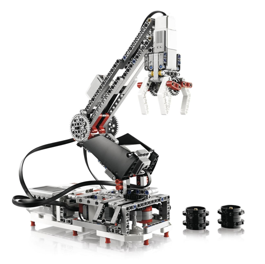
We have built the model of the robot arm.

Lego robot - the physical reality

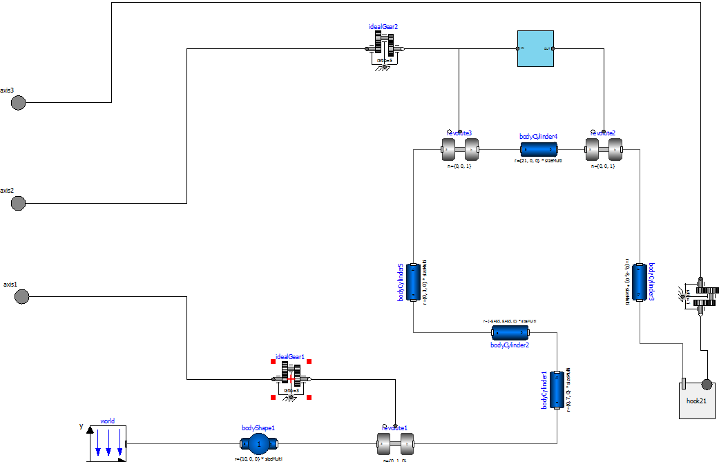
By decomposing the physical model into smaller pieces, we can get the hugh level modelica model, depicted in the following figure.

Mapping the robot arm to modelica

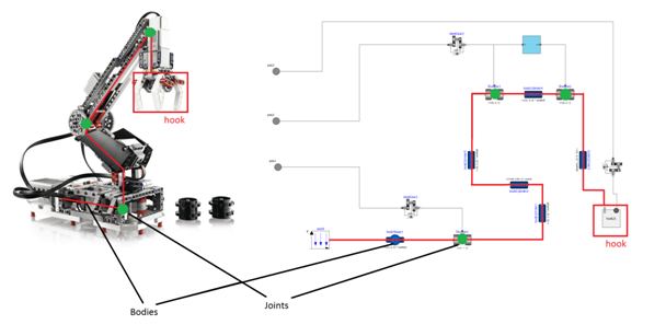
This hierarchical model can be further refined according to the parts of the physical component.

Two level of hierarchy of the physical model

We have used many different components of the library, we have parameterized them according to the measurements, and what we got is quite close to reality. We have done measurements and the model could predict the real physics with only 2-3% of error. This is a quite good result 🙂

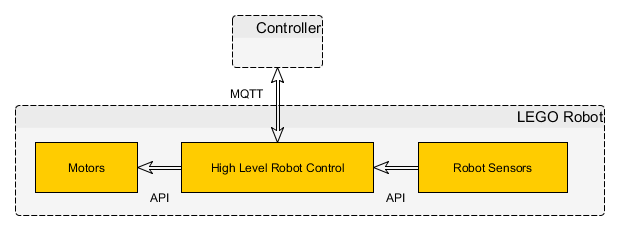
The simulaton is provided to the controller as a service running on a separate linux virtual machine. A virtual controller is developed which compiles the uploaded modelica files with the given parameters and computes the simulation. The results can be showed by the web server of this virtual machine or the results can be sent back to the controller.

the overview of the architecture is depicted on the next figure.

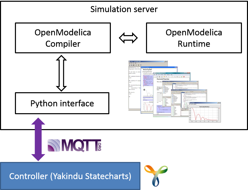
This way the simulation at design and also at runtime is available through a simple interface!

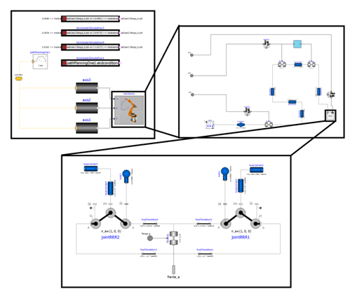
And now let’s show a simple simulation scenario! The model of the next picture is being simulated.

image

The angle of the three motors in the function of time is depicted on the next picture.

image

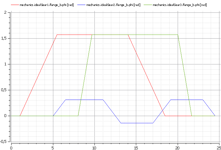
As it can be seen, the three motors can work independently with different speed! Note that this is just a simple example where only some parameters are examined. However, the tool is able to evaluate more complex parameters and movements of the system.

Simulation is a useful feature both at design and also at runtime, various questions regarding the path of the robot arm then can be answered!

The integration of the Lego robot with the controller: using MQTT from Python

In the Lego robot subproject of the MoDeS3 it was important to integrate the sensor information from the Lego sensors, the control and also the logic responsible for the safety. For this purpose, we have implemented an advanced control protocol in Python. This script runs on an embedded Linux distribution, called EV3dev. With this operating system we can utilize the Lego devices connected to the EV3 brick, while have access to all generic Linux packages, like the mosquitto broker.

The simplified overview of depdendecies is depicted on the next picture:

Overview

Our logic is able to detect when the motors are overdriven, or the robot is getting to a twisted and dangerous position, and prevents it from further attacking its limits by stopping them. By this protocol other components can control the crane by MQTT messages, or stop it if any other sensor detects something dangerous.

The code snippet below runs in a cycle and if it notices chage in the state of the touch-sensor, sends a message through MQTT (Paho). If needed it also executes some safety routines.

using MQTT

Sensors of the hardware are depicted on the following figures: these sensors provide the information:

SensorSensor2

The solution is built modularly, each part is responsible for certain movements and sensor information. The control software enables the user to control any of the motors individually, and get back raw sensor data through MQTT. A safety modul is observes the behaviours and available information and intervenes if something goes wrong.

Controlling and ensuring safety of the Lego robot arm: the computer vision challenge

As the Lego robot arm executes a mission, information about the environment is required. Beside executing missions correctly, our goal is to detect any kind of danger caused by the robot. The goal is twofold: the robot has to know when to execute a mission i.e. the object to be moved is at the right place. Second, it has to stop when some dangerous situation happens, for example a human is present near to the robot.

We are building the monitoring infrastructure of the robot arm based on computer vision technologies. OpenCV helps us detecting and tracking the movements of the robot In case of a moving robot, no other moving objects should be there. In addition, computer vision will detect if the object to be transported is in the proper place to handle by the robot.

First time we built only a robot arm with limited functionality. According to the experiences, we have totally rebuilt it.

Rebuilding the robot was a big step forward for the project’s computer vision goals. Now, we are able to detect the orientation and also the movement of the arm, without markers.

The new concept is to put on some Lego element in a combination to form a larger component with distinctive shape and colour. The camera observes the whole loading area from the top, and searches for the elements.

Using the same camera frames, we can detect the orientation of the gripper and find the cargos and the train.

For the gripper we needed a marker and that Lego element which we talked about before. The marker is directly connected to the gripper’s motor, so it is moving with the gripper during the rotation and other movements. The orientation is compared to the arm’s orientation so it won’t change during the movement of the arm, only the rotation influences its settings. The marker is a black circle, therefore we replaced the color detection with circle detection for this case.

Cargo has distinctive color.

In the following picture the output of the various steps of the process is depicted.

Output of the image processing steps

In the following we just sketch the working of the detection algorithms. Transforming the picture of the camera to HSV (Hue-Saturation-Value) representation. This will serve as a base representation for further processing. The next step is to decompose the picture according to the information we are looking for. In order to ease the tasks of the further processing, the picture is cut into pieces: The Lego arm, the gripper and also the object to be moved will be in different pieces of the picture.

Detecting the various objects of interest, we need to assess the color and the size of the objects in the picture: this is assessed at the next phase of the processing.

Edge detection algorithms search for the contour of the objects. Pattern matching algorithms try to find rectangles in the picture.

Numerical filters than used to sort the found objects (rectangles) according to their size. From the filtered objects, some special heuristics filter those object which are likely to be the searched object, namely the arm, the gripper and the load to be moved.

The movement of the arm is traced by reducing the problem to finding the moving rectangles in the filtered picture. Computing averages and tracing the middle point of the objects provide quite precise results.

So, as you might see, many algorithms work on the control and safety assurance of the Lego robot arm. Despite its complexity, it works well in practice!