

Model-based Demonstrator for Smart and Safe Systems


In the previous parts of Statecharts are everywhere series we discussed a lot of things. First, we talked about what xtUML BridgePoint Editor is, and how we designed the ‘safety logic’ with it. Second, we talked about the reasons why we switched from BridgePoint to YAKINDU Statechart Tools (SCT). Third, we introduced YAKINDU Statechart Tools.
Now, we are going to talk about the validation features delivered with SCT, and our extensions: validation based on incremental graph matching, and verification based on timed automaton formalism.
YAKINDU Statechart Tools (SCT) comes with a Validation framework that ensures the detection of unreachable states, dead ends and references to unknown events. These validation constraints are checked live during editing [1].
This framework is based on the Xtext’s Validation features that provide both syntactical and semantical validation. The syntactical correctness of any textual input is validated automatically by the parser and any broken cross-references can be checked generically [2].
Semantical validation means the developer of the grammar (that can be either textual, or graphical) can write validation rules in Java language for model elements. These rules are applied on the model and if they are not justified, then an error message is shown in the editor. More on validation can be read in the documentation of Xtext.
This way it can be ensured, that the model is valid, because it meets the well-formedness constraints it was set against.
After the introduction, let us see, what validation rules are built in SCT [3]. They mostly inherit from the semantics of (UML) statecharts, that is a well researched area.
Some other rules that are applied on the SCT model as well [4], but they do not necessarily come from the statechart semantics.
Bence, who is a friend of ours has extended the validation rules mentioned before with new ones. But these rules were composed using EMF IncQuery and are applied by its Validation Framework, rather than the Xtext Validation Framework.
EMF-IncQuery is a framework for defining declarative graph queries over EMF models, and executing them efficiently without manual coding in an imperative programming language such as Java.
With EMF-IncQuery, you can:
More on the EMF IncQuery Validation Framework can be read in its documentation.

Bence composed new validation rules in the IncQuery’s declarative query specification laguage. These rules are applied on the statechart model. If a rule is violated by the referred model then an error message is displayed next to it.
So how is IncQuery supposed to be used for validation? We are going to show you in an example.

The first pattern is responsible for returning declared events that are not used in the state machine. The validation message is defined by the Constraint annotation above the first pattern. The second pattern is an auxiliary pattern.
First of all, let us talk about how to define IncQuery patterns. Let us take a look at the first pattern. Note, that the pattern name must be preceded by the „pattern” keyword. Between parantheses we must declare what nodes of the instance model we want access to. Naturally, the given name must appear in the pattern body and refer to a node type.
„Event : EventDefinition” says that we will want access to the nodes that we refer to as „event” in the pattern body and they are instances of „EventDefinition”. Then, the pattern body must be constructed. Each line states something about the result set. „EventDefinition(event);” states, that through „event” we only want to refer to nodes that are instances of „EventDefinition”. Patterns can be reused with the „find” keyword. This can be imagined as a function call: all of the statements of the called pattern will be applied in the pattern we call it from. To invert the meaning of the find keyword it must be preceded by the „neg” modifier. It forbids the match of the called pattern with the given parameterization.
In the second pattern we want to return nodes, instances of„EventDefinition”, that are not referred by any instance of „FeatureCall” or „ElementReferenceExpression”. FeatureCall.feature(_featureCall, event);” states that there must be a „FeatureCall” instance that has a „feature” reference to „event” (which is as stated before is an instance of EventDefinition). The statements are in a logical AND relation. As you can see, OR relation can be declared as well using the „or” keyword.
To mark the unused events for the Yakindu user a Constraint annotation must be defined. In the annotation the target editor, the message and the severity must be given apart from the elements that we want to mark. The elements are returned by the pattern the annotation is bound to.
The high-level purposes of the validation rules are to reduce the ambiguity and nondeterminism of the design models and to avoid bad design practises and structures.
Verification is used for making sure the designed system meets its requirements, and work as we imagined. Although there are a lot of verification techniques, we use timed automaton formalism and computational tree logic.
We chose timed automaton formalism because it is similar to the formal operation of YAKINDU statecharts (in theory), and we already have practise with UPPAAL. UPPAAL is an industry-wide known tool for formal verification of real-timed systems by timed automata.
UPPAAL uses a subset of Computational Tree Logic (CTL for short). The UPPAAL query language consists of a path formula quantified over none, one, more or all paths of the model. Specifications used in UPPAAL can be classified into reachability, safety and liveness properties. Next figure illustrates the formulae supported by UPPAAL. Filled circles represent those states for which a given state formulae hold.

Besides the validation rules, Bence developed a model transformation plugin for Yakindu as well. The plugin transforms a chosen SCT model into a timed automaton, and automatically generates CTL expressions for formal verification.
The model transformation plugin is continuously evolving to support all features (e.g. choice, entry, exit nodes, parallel regions, etc) of statecharts.
As an example the design and formal models of main region of Section statechart is depicted in the next figures.
Design model:

Formal model:

Finally, the formal verification result of the timed automata transformed from the Section statechart is depicted in the next figure.

In the previous entries, we already talked about that we would use Beaglebone Black units to run our safety logic, but in my opinion, these systems have a problem: they could work only if you provide them 5V power source. Of course it’s not that big problem if you are starting a new project based on these computers, because you could choose your power source as you want.
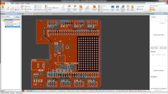
But in our case, we already had a 12V power source under the hood. Furthermore we should use 12V source to feed railway lights, so we had to find out a solution. In one of my previous entries I already made a prototype, which would do the trick for us. But we need to install this solution somehow on the Beaglebone, so this weekend I designed a PCB (printed circuit board) to place this solution.
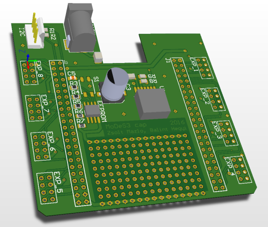
Here is the final version:
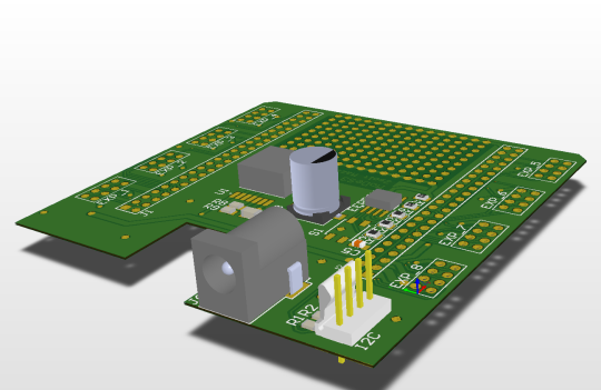
Disclaimer: I may call it final version, but every evening I find something to modify. So this is maybe not the final version, but it will have no major modification in the near future.
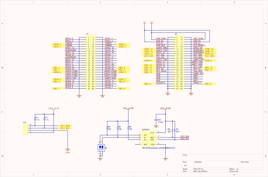
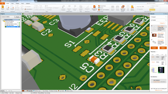
At the beginning, I started to design our board with Eagle: this program is a lightweight designer for PCBs, and it’s lovable for its multiplatform quality, so it was perfect for me. But I merely started to design anything, one problem came after another. The biggest of all, I couldn’t find any libraries which would give the footprint of our chosen power module, the TI LMZ22005.
Intermezzo: we chose this module because it’s super easy to install on any design. You should only use some capacitors and resistors, and you are done (not to mention, the values of these elements are also provided by TI).
So, I had to make a decision: shall I go on with eagle and design the footprint of the power module myself, which hold the danger of faulty design, or choose another program and learn how to use it. Bálint pointed out that he heard good reviews about the Altium Circuit Maker program, and after a short test, we decided we should give it a try.
If you are starting to use a new software, first it’ll be totally unfamiliar for you. So you should learn how it works, how can you accomplish what you want, etc. For PCB designer applications, it’s more difficult: they have great set of functionality, tremendous preferences. That’s why for the first couple of hours I had to work as “we were just getting to know each other”.
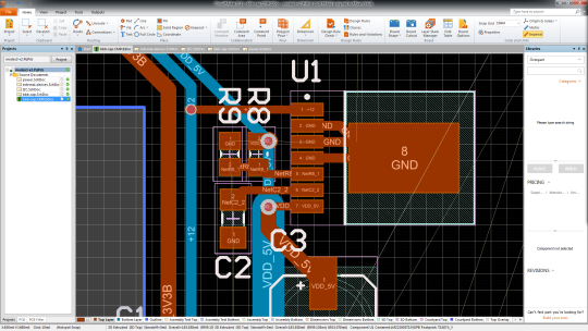
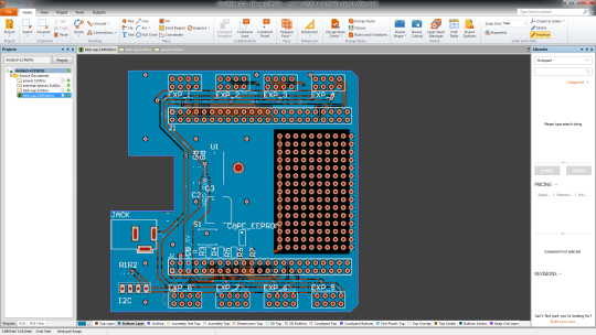
But in the end, I managed to design the circuit. I chose every elements of it (it’s a big help that you have oodles parts from Octopart which you could use), I “just” had to route the PCB itself.
So, after the logical design, you have to place every element on the board and figure it out how you should make connections between them – that’s the routing. For a senior PCB designer, it’s not that hard to do, but for me, who had no experience at all in making PCBs and in the program also, I had my lesson.
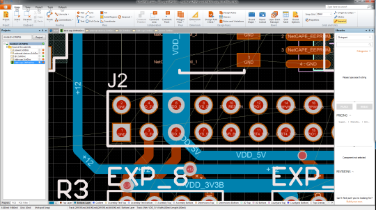
This work was all about patience: routing every single wire to the right place was not that hard, just time-killing, because measuring distances, the calculating and designing the perfect layout was hard. Not because of the math: if you do something wrong the board would be useless, you have to fix the problems and print it out again, but it costs a lot of money, so you kind of have only one shot. In the consciousness of this I took my time and measured everything twice, rethought anything at least once and I pursued the perfect solution.
After finishing it, I talked to people who had more experience in designing, took their pieces of advice, and now I am waiting for the bid and I am hoping that it will not take us into bankruptcy.
Hi everyone! Let me start by introducing our project called MoDeS3, which stands for Model-based Demonstrator for Smart and Safe Systems. The main goal of our IoT challenge application is to demonstrate the many cool and innovative ways in which open source modeling tools can be used for systems development in the age of Internet-of-Things.
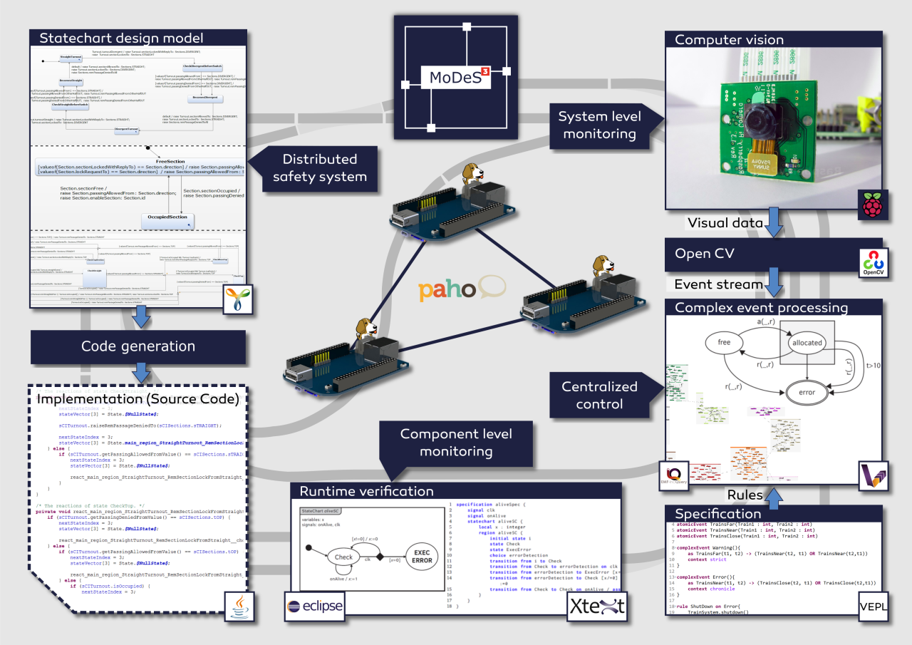
Our case study is a railway system: users can control trains arbitrarily as long as it is not dangerous. Accidents and dangerous situations are detected using sensors embedded into the track: they sense the trespass of the trains and send this information to the controllers. It is important to note that this is just local information, so we have to ensure that it will be shared between the components. We employ six BeagleBone Black (BBB) embedded computers to run the safety logic, configured as a distributed system, where each BBB is responsible for some track sections.
As you can imagine, the real software engineering challenge is how to develop the distributed safety logic. We use the open source Yakindu Statecharts tool to design the software components. It is much easier than manual programming, as it provides a code generator to produce C or Java code.
In order to supercharge the expressive power of Yakindu models, we have developed custom validation and verification rules. For this purpose, we used the open source EMF-IncQuery engine. Our IncQueries can be used to analyse the well-formedness of the models, for example to check if the state chart is deterministic and complete. This turned-out to be a useful feature as many design time errors were found, well before deployment and debugging even began!
In addition to the validators, we have also developed model transformations to generate formal models from the state chart models. These formal models, together with associated model checking tools such as UPPAAL, are used to check the deadlock freedom and reachability of the states in the model. In the future, we plan to work more in this direction, in order to automatically analyse other properties such as fault-tolerance properties. We developed the model transformations using the VIATRA framework.
To make distributed systems work in practice, we need communication channels. For this project, we are going to use MQTT for its simplicity, reliability and flexibility. The open source Eclipse Paho framework helps us in establishing and maintaining the communication between the components.
In order to provide system-wide safety guarantees, we plan to build an additional layer on top of reliable communication channels, to facilitate runtime monitors. These smart components will evaluate the behaviour of the local components, and run locally on the PRU 32-bit microcontrollers of the BBBs. They will analyse if the communication works correctly and there is no problem within the controller itself.
To augment local monitors, the overall system status will be monitored using computer vision techniques. For this purpose, we attached a camera to a stage above the tracks that will observe the movement of the trains. The video stream is processed by OpenCV, a state-of-the-art open source computer vision library. We have implemented train recognition algorithms to detect the position of the trains.
The combination of local monitoring data and computer vision data will be aggregated on the system level and processed using complex event processing (CEP). The role of this high-level monitoring technique is to integrate multiple monitoring data sources and make sure that if the distributed safety logic does not work correctly, this additional level of logic can still bring the system to a safe state. Our system-level safety framework will be built using an open source complex event processing engine called VIATRA-CEP.
Model Railway Track Side Perspective
Model Railway Onboard Footage #2
Model Railway Onboard Footage #1