


Model-based Demonstrator for Smart and Safe Systems
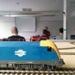
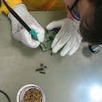
Now, that the Open IoT Challenge is over, we have some spare time, therefore I try to explain for you how the hardware works and how was made. It won’t be a very long post, you shouldn’t read long paragraphs about electrons or voltage, but I will insert a tons of pictures into it, I should insert a read more link here. But trust me: it is worth watching them!
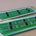
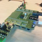
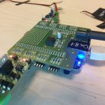
Previously one of my colleague, Bálint already wrote about why the Beaglebone Black board is so amazing, but in an other post I mentioned our little problem with the hardware – so I did managed to make a Cap for the beagle to make it Superman Superbeagle.
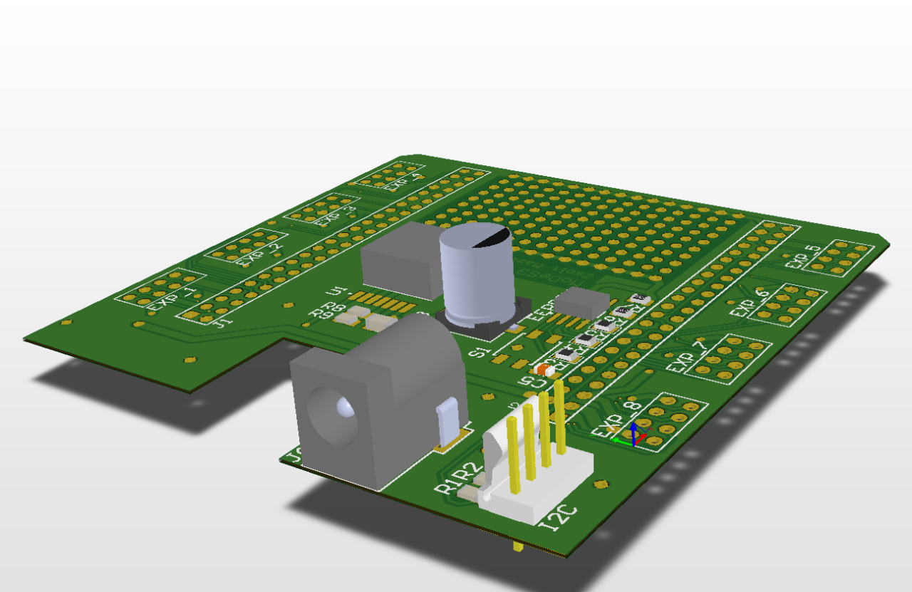
The design:
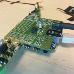
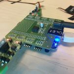
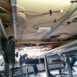
And the reality:
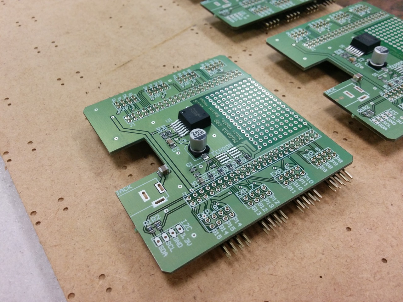
With this Cap, the Beaglebones could accept any power source between 7V and 20V, we have 8 pin headers to attach expander panels… oh wait, did I mentioned that we designed expanders also? No? My bad.
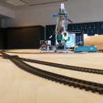
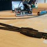
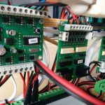
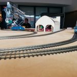
One of the many responsibility of the hardware is that it need to sense somehow the status of the turnouts. These informations are highly important: some cases, in which trains are moving towards each other, they could collide, so we should stop them; but if the turnout is in the right position, then we could pass one of them through the turnout and even avoid the collision. With this knowledge, we could make the movement of the trains continuously beside the safe operation.
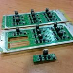
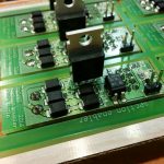
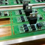
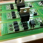
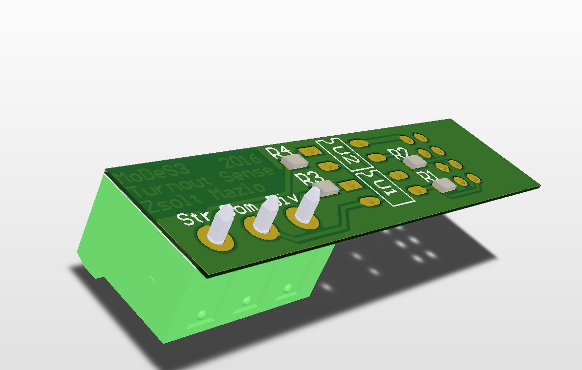
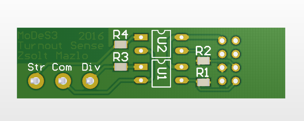
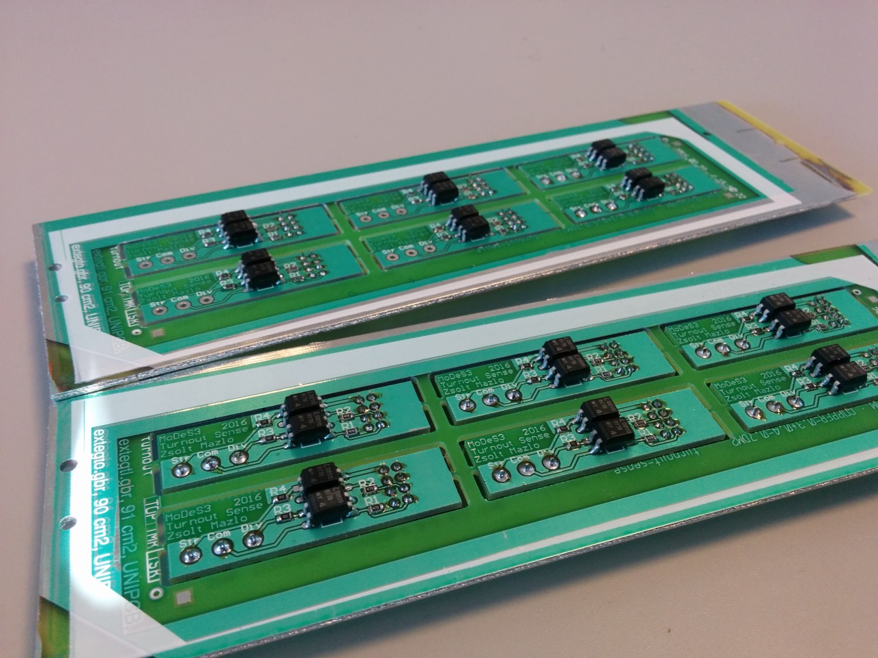
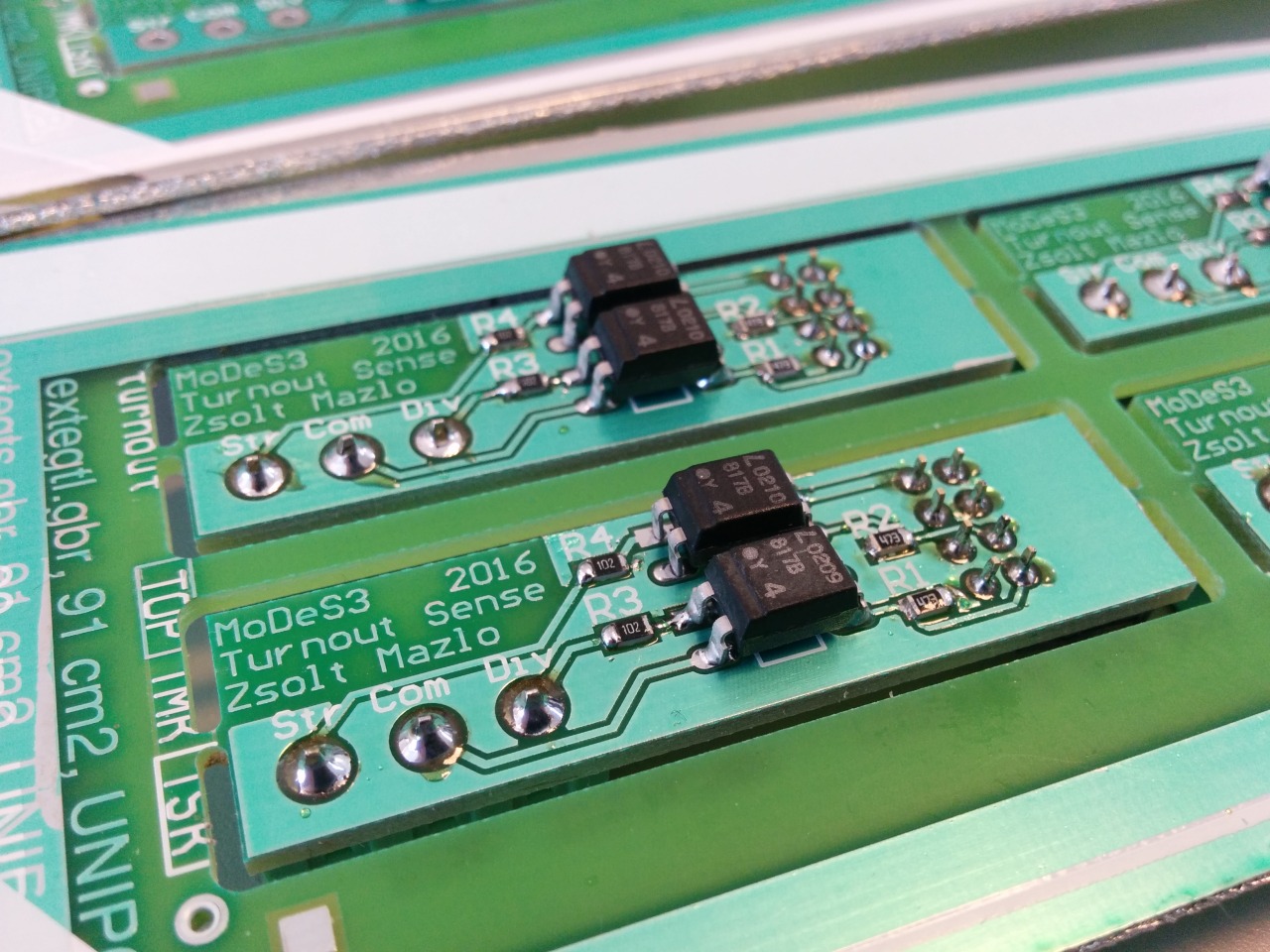
Therefore we made some measurements about how the turnout actuators are work and after that we created a PCB to handle this.
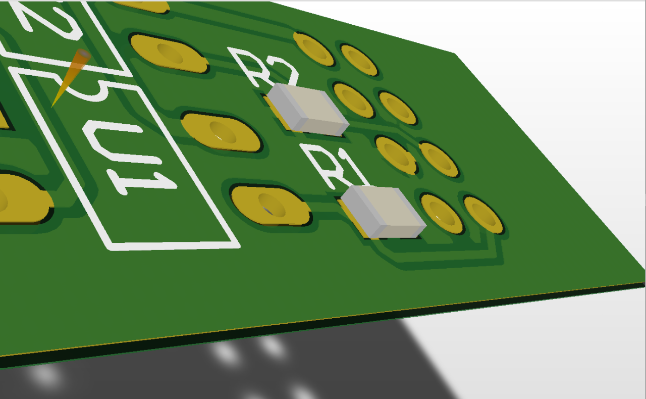
Here is the design:
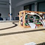
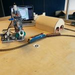
And the reality:
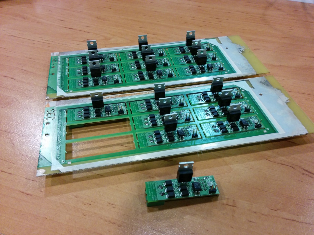
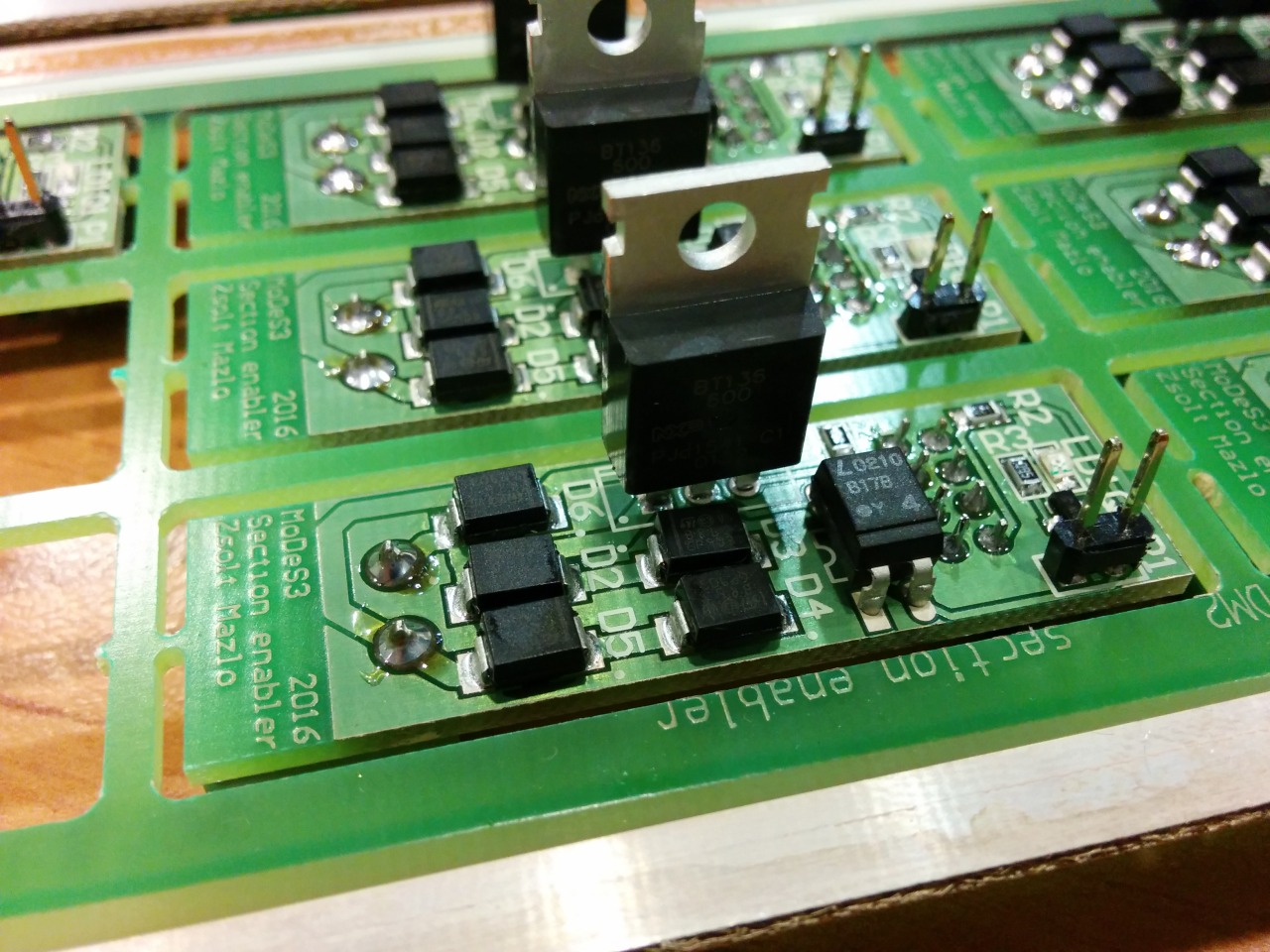
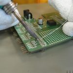
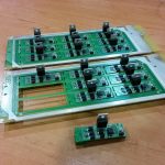
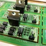
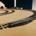
Okay, let assume that we are getting every information about the track that we need: the location of the trains, the turnouts’ status, and so on, and one time, we need to stop one train: but how, you may ask. That’s the reason why we designed and assembled the section enabler or disabler PCBs: in the near past I wrote about the mechanism.
Design:
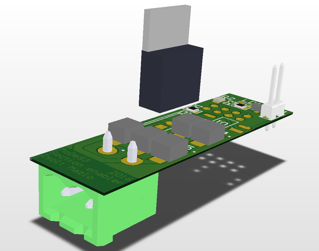
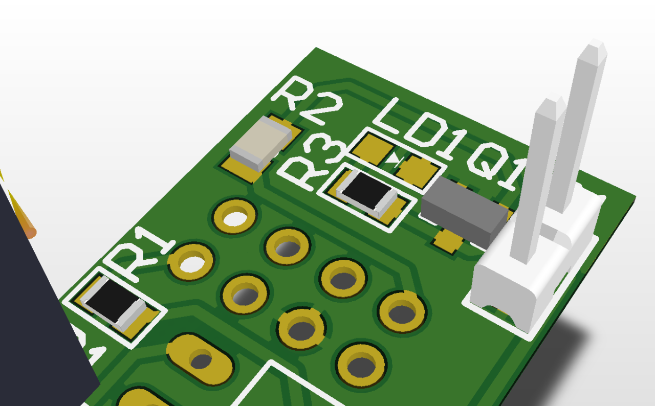
Reality: